Page 132 - Mechanical Engineer's Data Handbook
P. 132

THERMODYNAMICS  AND  HEAT TRANSFER                                                121


                                                                         I
                                                     Coding
                                                     water jacket-.


                                                     Cooling water-
                                                     jackel                 Combustion
                                                     zmiw-I -               Push md
                                                                            chamber
                                                       Piston-
                                                       Cylinder -
                  Crank angle, e
                Typical timing diagram
         where:  N =number  of  revolutions  per  second,
         n =number  of  cylinders,  A, =piston  area  (m'),
         L = stroke (m)

         Torque T=FR (Nm)
                                                      Sump
         where: F=force on brake arm (N), R= brake radius
         (m).                                                 Four-stmke engine
         Brake power  Pb=2nNT  (watts)
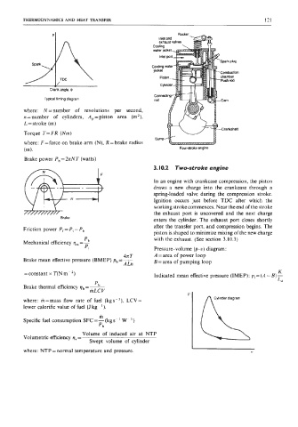
                                                     3.10.2   Two-stroke engine

                                                     In an engine with crankcase compression, the piston
                                                     draws  a  new  charge  into  the  crankcase  through  a
                                                     spring-loaded valve  during  the  compression  stroke.
                                                     Ignition  occurs  just  before  TDC  after  which  the
                                                     working stroke commences. Near the end of the stroke
         7f/m7n3r Brake                              the  exhaust  port  is  uncovered  and  the  next  charge
                                                     enters the  cylinder.  The exhaust  port closes shortly
                                                     after the transfer port, and compression begins. The
         Friction power  P, = Pi - P,
                                                     piston is shaped to minimize mixing of  the new charge
                                                     with the exhaust. (See section  3.10.3)

                              '
                            b
         Mechanical efficiency )I,,, = -
                              Pi                     Pressure-volume  (pu) diagram:
                                           4n T      A =area of  power  loop
         Brake mean effective pressure  (BMEP) pb=-   B = area of  pumping loop
                                           ALn
         =constant x T(N m ~  *)                                                               K
                                                     Indicated mean effective pressure (IMEP): pi = (A - B) -
                                                                                               L*
                                 'b
         Brake thermal efficiency 9  -~
                             ,-mLCV
         where:  m=mass  flow  rate  of  fuel  (kgs-I),  LCV=
         lower calorific value of  fuel (J kg-').
                                   m
         Specific fuel consumption SFC =-  (kg s- ' W- ')
                                   Pb
                             Volume  of  induced  air  at  NTP
         Volumetric efficiency )I,, =
                               Swept  volume  of  cylinder
         where: NTP = normal temperature and pressure.                                V
   127   128   129   130   131   132   133   134   135   136   137