
Page 136 - Mechanical Engineer's Data Handbook
P. 136
THERMODYNAMICS AND HEAT TRANSFER 125
3. I I .2 Multi-stage compressor
Intercooler
For S stages, the ideal pressure for each stage is:
Isentropic work Wi=p, V, (],Y) (I (3
1)
-
for which ~
Sn
Wi
y
Indicated power Pi =- mR( T, - T, ) Efficiency q = - - 1)
=
(n- 1) W y-1 (r-1)
Typical efficiencies
The efficiency is increased by using more than one r 1.2 1.6 2.0
stage if intercooling is used between the stages to
reduce ideally the temperature of the air to that at the v 0.95 0.84 0.77
first stage inlet. The cylinders become progressively
smaller as the pressure increases and volume de-
creases. Pressure ratio < 2.0 for one stage
~3.0 for two stages
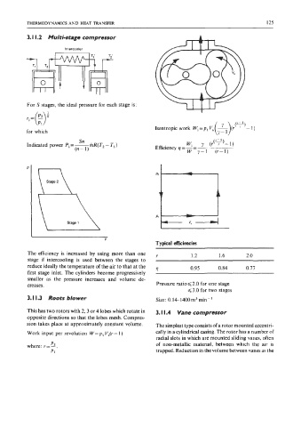
3.1 1.3 Roots blower Size: 0.14-1400m~rnin-'
This has two rotors with 2,3 or 4 lobes which rotate in 3. I I .4 Vane compressor
opposite directions so that the lobes mesh. Compres-
sion takes place at approximately constant volume. The simplest type consists of a rotor mounted eccentri-
Work input per revolution W=p, VS(r- 1) cally in a cylindrical casing. The rotor has a number of
radial slots in which are mounted sliding vanes, often
P
where: r=L. of non-metallic material, between which the air is
P1 trapped. Reduction in the volume between vanes as the