
Page 138 - Mechanical Engineer's Data Handbook
P. 138
THERMODYNAMICS AND HEAT TRANSFER 127
3. I3 Refrigerators
Two basic types are considered, the ‘vapour compres- and temperature and finally evaporated in an ‘evapor-
sion refrigerator’ and the ‘gas refrigerator’. The former ator’ before re-entry into the compressor. The cycle is
consists of a compressor followed by a condenser similar to the Rankine cycle in reverse.
where the refrigerant is liquified at high pressure. It is The gas cycle is the reverse of a closed gas-turbine
then expanded in a ‘throttle valve’ to a lower pressure cycle, Le. the constant pressure or Joule cycle.
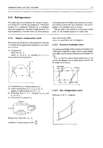
3.13. I Vapour compression cycle Heat removed Q = mRE
where: m = mass flow rate of refrigerant
The process can be shown on the temperature entropy
(T-s) chart for the appropriate refrigerant, e.g. ammo- 3.13.2 Pressure-enthalpy chart
nia or Freon.
The pressure-enthalpy chart is a more convenient way
(1) Compression of showing refrigeration cycles. Work in and refriger-
Work W=h,-h, ation effect can be measured directly as the length of a
where: h,=h, at p,, h,=enthalpy at p2, s2=s1 line.
(since isentropic compression).
If p,, pz and the under cooling temperature T4 are
known, the diagram can be easily drawn and RE and
W scaled off as shown.
p p Undercooling
Undercooling
RE
I RE
S
h
(2) Condensation at constant pressure pz.
(3) Under-cooling from T3( = T, at p2) to T4.
Degree of undercooling AT= T3 - T4 3.13.3 Gas refrigeration cycle
(4) Throttling from 4 to 5. Therefore h,=h4 and
h4=h, at T4. Referring to the T-s diagram:
(5) Evaporation at pressure p,.
Condenser
2 Compressor
Throttle
Evaporator
Refrigeration effect RE = h, - h,
RE
Coefficient of performance COP = -
W