
Page 133 - Mechanical Engineer's Data Handbook
P. 133
122 MECHANICAL ENGINEER'S DATA HANDBOOK
TDC
Crankcase diagram
where: K =indicator constant.
Indicated power P,=p,A,LNn
271 T
Brake mean effective pressure (BMEP) p --
b-ALn
Other quantities are as for the four-stroke engine. BOC
Compression-ignition engines
Two-stroke engine
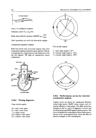
Both four-stroke and two-stroke engines may have
compression ignition instead of spark ignition. The air I =inlet angle (approx. 80')
is compressed to a high pressure and temperature and E =exhaust angle (approx. 120")
the fuel injected. The high air temperature causes T= transfer angle (approx. 100")
combustion.
TDC
BDC
3.10.4 Performance curves for internal
combustion engines
3.10.3 Timing diagrams
Typical curves are shown for mechanical efficiency
Four-stroke engine versus brake power, BMEP versus torque, and vol-
umetric efficiency versus speed. The effect of mixture
IO =inlet valve opens strength on the pv and pS diagrams is shown and
IC =inlet valve closes curves of power and MEP against speed are given. The
S =spark occurs curve of specific fuel consumption versus brake power,
EO=exhaust valve opens known as the 'consumption loop' shows the effect of
EC = exhaust valve closes mixture strength on fuel consumption.