
Page 135 - Mechanical Engineer's Data Handbook
P. 135
124 MECHANICAL ENGINEER'S DATA HANDBOOK
3. I I Air compressors
The following deals with positive-displacement-type pressures and the Roots blower and vane compressor
compressors as opposed to rotodynamic types. The are most suitable for low pressures.
reciprocating compressor is the most suitable for high
TP
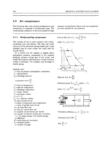
3. I I. I Reciprocating compressor Freeair flow Q=(V,-V,)--NNZ
Tl P
This consists of one or more cylinders with cranks, where: V,=(V,+ VJ.
connecting rods and pistons. The inlet and outlet
valves are of the automatic spring-loaded type. Large
cylinders may be water cooled, but small ones are "1 c b
usually finned. TZ
Air is drawn into the cylinder at slightly below
atmospheric pressure, compressed to the required
discharge pressure during part of the stroke, and
finally discharged at outlet pressure. A small clearance
volume is necessary. The cylinders may be single or
double acting.
Symbols used:
p = free air pressure (atmospheric conditions) "a V
pi =inlet pressure
p2 =discharge pressure
P2
r =pressure ratio = -
n
P1 Indicated power Pi=-mR(T2- T,)
T= free air temperature (n- 1)
T, =inlet air temperature
T2 =discharge temperature
V, = swept volume
Vc =clearance volume
v, = V, + Vc
Va - Vd =induced volume
R = gas constant for air
n =index of expansion and compression
y = ratio of specific heats for air
rit = air mass flow rate
Q = free air volume flow rate
vc
N = number of revolutions per second Volumetric efficiency qv = 1 - - (14 - 1 )
Z = number of effective strokes per revolution Vs
(= 1 for single acting; 2 for double acting)
vc
q =efficiency Clearance ratio CR = -
W=work done per revolution VS
Pi = indicated power Also --=re '
'd
S=number of stages VC