
Page 201 - Mechanical Engineer's Data Handbook
P. 201
MANUFACTURING TECHNOLOGY 189
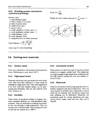
5.5.3 Grinding process calculations Power P=- FU
(cylindrical grinding) loo0
P
Symbols used: Energy per unit volume removed E=- (J mm-3)
t = chip thickness (mm) bfv
f=feed or depth of cut (mm)
p=pitch of grains (mm)
b = width of cut (mm)
P = power (watts)
u = wheel peripheral velocity (mm s- ')
u=work peripheral velocity (mm s-l)
d = wheel diameter (mm)
D = work diameter (mm)
F = tangential force on wheel (newtons)
V
minus sign for internal grinding
~~ ~
5.6 Cutting-tool materials
5.6.1 Carbon steels 5.6.4 Laminated carbide
Their use is restricted to the cutting of soft metals and These consist of a hard thin layer of titanium carbide
wood. Performance is poor above 250°C. bonded to a tungsten carbide body. The surface has
very high strength at high temperature, whilst the body
5.6.2 High-speed StMIS has high thermal conductivity and thus efficient re-
moval of heat.
These are used extensively, particularly for multi-point
tools. They have been replaced to a large extent by 5.6.5 Diamonds
carbides for single-point tools. Their main application
is for form tools and complex shapes, e.g. for gear- These are the hardest of all cutting materials with low
cutting and broaching. They are also used for twist thermal expansion and good conductivity. They are
drills, reamers, etc. twice as good as carbides under compression. A good
finish can be obtained with non-ferrous metals and
5.6.3 Carbides final polishing can be eliminated. Diamonds are
particularly good for cutting aluminium and mag-
These consist of powdered carbides of tungsten, tita- nesium alloys, copper, brass and zinc. They have a
nium, tantalum, niobium, etc., with powdered cobalt long life.
as binder. They are produced by pressing the powder
in dies and sintering at high temperature. They are
then ground to the final shape. They are generally used
as tips and can operate up to 1oo0"C.