
Page 21 - Mechanical Engineer's Data Handbook
P. 21
10 MECHANICAL ENGINEER’S DATA HANDBOOK
.+--@- Bolted joint in tension
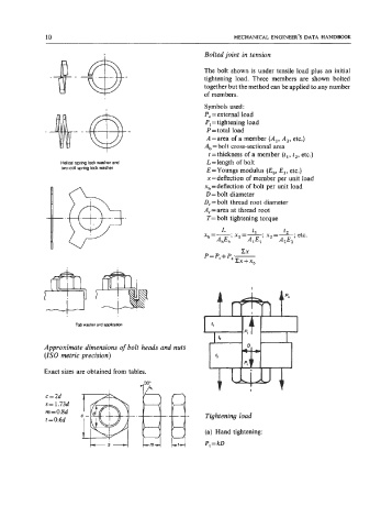
The bolt shown is under tensile load plus an initial
tightening load. Three members are shown bolted
together but the method can be applied to any number
of members.
Symbols used:
P, =external load
PI = tightening load
P=total load
A=area of a member (Al, A,, etc.)
A, = bolt cross-sectional area
t = thickness of a member (t,, t,, etc.)
t D, = bolt thread root diameter
L=length of bolt
Helical spring lock washer and
two-coil spring lock washer
E=Youngs modulus (E,, E,, etc.)
x=deflection of member per unit load
x, = deflection of bolt per unit load
D = bolt diameter
A, = area at thread root
T= bolt tightening torque
.@E.
L
t2
x,=-;
A,El
A,E,
At$,
EX
P = PI + P;- xl=-; tl x,=----; etc.
B
zx + x,
Tab washer and applihn
Approximate dimensions of bolt heads and nuts
(IS0 metric precision)
Exact sizes are obtained from tables.
c=2d
s = 1.73d
m = 0.8d Tightening load
t = 0.6d
(a) Hand tightening:
PI = kD