
Page 114 - Mechanical Engineers Reference Book
P. 114
Electrical safety 2/55
The timer can deliver currents of more than 100 mA, and it nology, number systems and interfacing techniques for digital
can therefore be used to drive a DIL reed relay directly. When computers.
such a relay is switched off, however, the back e.m.f. gene- The main advantages of the microprocessor-based system
rated by the relay coil could damage the timer. As a precau- are that the logical functions for a particular application can be
:ion, a diode is normally connected in parallel with the relay developed and implemented in software, as opposed to elec-
coil. in the opposite direction to the current flow. to absorb tronic hardware. In many instances the microprocessor-based
the high induced voltage. system may actually be the cheaper alternative to a hardwired
logic gate circuit. The software is easy to alter in the event of
2.3.32.2 Astable incorrect system operation and the complete system can be
tested as a simulation before being committed.
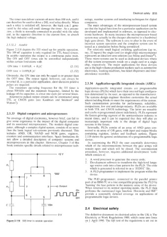
Figure 2.118 depicts the 555 wired up for astable operation. For relati\iely small logical switching applications (up to,
The 100 nF capacitor is only required for TTL-based timers. say, 32 inputs) the single-card (or single-chip) microcomputer
In astable operation the output is a continuous pulse train. represents an ideal low-cost solution (see Milne and Fraser”).
The ON and OFF times can be controlled independently These micro-systems can be used as dedicated devices where
within certain limitations with all the system components reside on a single card or a single
chip, respectively. The major applications for these devices
ON time = 0.693(R! + R,)C (2.131) are in the high-volume production markets such as automotive
OFF time = 0.693(R2)C (2.132) electronics; washing machines, bus ticket dispensers and time-
Obviously, the ON time can only be equal to or greater than attendance recorders.
the OFF time. The output signal. however, can always be
inverted if, in a particular application, short-duration positive
pulses are required. 2.3.34 Application-specific integrated circuits (ASICs)
The maximum operating frequency for the 555 timer is Application-specific integrated circuits are programmable
about 500 kHz and the minimum frequency, limited by the logic devices (PLDs) which have their internal logic configura-
leakage of the capacitor, is about one cycle per several hours. tion determined by the user, as opposed to the manufacturer.
Alterinative pulsed output circuits can be constructed using The systems design engineer therefore customizes the actual
TTL or CMOS gates (see Kaufman and Seidman8 and silicon building blocks to meet the requirements of the system.
Watson”). Such customization provides for performance. reliability,
compactness, low cost and design security. PLDs are available
in both TTL and CMOS technology. The latter are erasable
2.3.33 Digital computers and microprocessors and can be reprogrammed almost indefinitely. PLDs represent
the fastest-growing segment of the semiconductor industry in
No coverage of digital electronics, however brief, can fail to recent times, and it can be expected that they will play an
give some cognizance to the impact of the digital computer increasingly important role in the design of digital logic
and its associated microprocessor. The modern digital com- systems in the future.
puter, although a complex digital system. consists of no more Internally, PLDs consist of an array of AND gales con-
than the basic logical sub-systems previously discussed. This nected to an array of OR gates, with input and output blocks
includes AND, OR, NAND and NOR gates, registers, containing registers, latches and feedback options. Figure
counter:s. and communication interfaces. Space limitations do 2.119 shows the general architecture of a programmable logic
not allow a detailed description of computer systems and device.
microprocessors in this chapter. However, Chapter 3 of this In customizing the PLD the user essentially determines
book contains specific details related to microprocessor tech- which of the interconnections between the gate arrays will
remain open and which will be closed. The customization
procedure, however, requires additional development ’tools‘
which consists of:
1. A word processor to generate the source code:
2. Development software to transform the high-level langu-
age source code into a fuse pattern for the PLD. The code
which is generated is referred to as a ‘JEDEC’ file;
3. A PLD programmer to implement the program within the
device.
The PLD programmer, connected to the parallel printer
port of an IBM-PC or a true compatible programs the PLD by
‘burning’ the fuse pattern in the memory array of the device.
When returned to its normal operating mode, the PLD then
performs the customized logic function. Horowitz and Hill”
provide a reasonably detailed coverage on applications of
programmable logic devices.
“f 2.4 Electrical safety
I O ” The definitive document on electrical safety in the UK is The
Electricity at Work Regulations 1989, which came into force
Figure 2.118 555 timer in astable operation on 1 April 1990. The full text of the regulations is set out in