
Page 111 - Mechanical Engineers Reference Book
P. 111
2/52 Electrical and electronics principles
Inputs Output changes
J Q-
S R Qn + Qn+l On +&+, . CK
0 0 o+o 1+1 -
0 0 1+1 o+o K C Q
0 1 o+o 1+1
0 1 1-0 0+1
1 0 0+1 1 +o
1 0 1+1 o+o
Inputs outputs
1 1 Not available
1 1
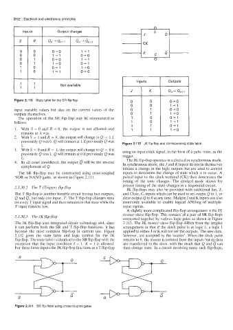
J K Qn- Qn+1
Figure 2.110 State table for the SR flip-flop o+o
1+1
input variable values but also on the current values of the o+o
outputs themselves. 1 +o
The operation of the SR flip-flop may be summarized as 0+1
follows: 1+1
0+1
1. With S = 0 and R = 0, the output is not affected and 1 +o
remains as it was.
2. With S = 1 and R = 0, the output will change to Q = 1 if
previously Q was 0. Q will remain at 1 if previously Q was Figure 2.112 JK flip-flop and corresponding state table
1.
3. With S = 0 and R = 1, the output will change to Q = 0 if using an input clock signal, in the form of a pulse train, as the
previously Q was 1. Q will remain at 0 if previously Q was trigger.
0. The JK flip-flop operates in a clocked or synchronous mode.
4. In all cases considered, the output a will be the inverse In synchronous mode, the J and K inputs do not in themselves
complement of Q.
initiate a change in the logic outputs but are used to control
The SR flip-flop may be constructed using cross-coupled inputs to determine the change of state which is to occur. A
NOR or NAND gates, as shown in Figure 2.111. pulsed input to the clock terminal (CK) then determines the
timing of the state changes. The clocked mode allows for
precise timing of the state changes in a sequential circuit.
2.3.30.2 The T (Trigger) flip-flop JK flip-flops may also be provided with additional Set, S,
The T flip-flop is another bistable circuit having two outputs, and Clear, C, inputs which can be used to set output Q to 1, or
Q and Q, but only one input, T. The T flip-flop changes state clear output Q to 0 at any time. Muliple J and K inputs are also
on every Tinput signal and then remains in that state while the commonly available to enable logical ANDing of multiple-
T input remains low. input signals.
A slightly more complicated flip-flop arrangement is the JK
master-slave flip-flop. This consists of a pair of SR flip-flops
2.3.30.3 The JK flip-flop
connected together by various logic gates as shown in Figure
The JK flip-flop uses integrated-circuit technology and, since 2.113. The JK master-slave flip-flop differs from the simpler
it can perform both the SR and T flip-flop functions. it has arrangement in that if the clock pulse is at logic 1, a logic 1
become the most common flip-flop in current use. Figure applied to either J or K will not set the outputs. The new data,
2.112 gives the state table and logic symbol for the JK however, are accepted by the ‘master’. When the clock pulse
flip-flop. The state table is identical to the SR flip-flop with the returns to 0, the master is isolated from the inputs but itsdata
exception that the input condition J = 1, K = 1 is allowed. are transferred to the slave, with the result that Q and Q can
For these latter inputs the JK flip-flop functions as a T flip-flop then change state. In a circuit involving many such flip-flops,
R
Q
S
Figure 2.1 11 SR flip-flops using cross-coupled gates