
Page 107 - Mechanical Engineers Reference Book
P. 107
3
2/48 Electrical and electronics principles
+E)
A.B+C.(D
c. (D + E)
E kd?
1
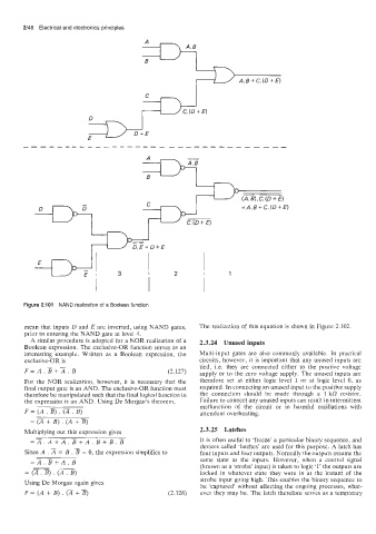
Figure 2.101 NAND realization of a Boolean function
mean that inputs D and E are inverted, using NAND gates, The realization of this equation is shown in Figure 2.102.
prior to entering the NAND gate at level 4.
A similar procedure is adopted for a NOR realization of a 2.3.24 Unused inputs
Boolean expression. The exclusive-OR function serves as an
interesting example. Written as a Boolean expression, the Multi-input gates are also commonly available. In practical
exclusive-OR is circuits, however, it is important that any unused inputs are
F=A.B+T.B (2.127) tied, i.e. they are connected either to the positive voltage
supply or to the zero voltage supply. The unused inputs are
For the NOR realization, however, it is necessary that the therefore set at either logic level 1 or at logic level 0, as
final output gate is an AND. The exclusive-OR function must required. In connecting an unused input to the positive supply
therefore be manipulated such that the final logical function in the connection should be made through a 1 kfi resistor.
the expression is an AND. Using De Morgan’s theorem, Failure to connect any unused inputs can result in intermittent
F = (A . B) (2. malfunction of the circuit or in harmful oscillations with
.
B)
attendant overheating.
+
= (;I B) . (A + B)
Multiplying out this expression gives 2.3.25 Latches
-
=A.A+A.B+A. B+B.B It is often useful to ‘freeze’ a particular binary sequence, and
devices called ‘latches’ are used for this purpose. A latch has
Since A .A = B . B = 0, the expression simplifies to four inputs and four outputs. Normally the outputs assume the
- same state as the inputs. However, when a control signal
=A.B+A.B
- (known as a ‘strobe’ input) is taken to logic ‘1’ the outputs are
= (2. E) . (AT) locked in whatever state they were in at the instant of the
strobe input going high. This enables the binary sequence to
Using De Morgan again gives be ‘captured’ without affecting the ongoing processes, what-
+
F = (A + B) . (2 B) (2.128) ever they may be. The latch therefore serves as a temporary