
Page 105 - Mechanical Engineers Reference Book
P. 105
A - w
-
T
T
Tea
--
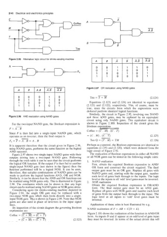
Figure 2.95 Alternative logic circuit for drinks-vending machine - - __ -
A B A B A.6 AB
A 0 0 1 1 1 0
F 0 1 1 0 0 1
FO
1 0 0 1 0 1
B 1 1 0 0 0 1
Figure 2.97 OR realization using NAND gates
1
0
31 1 Tea = T + (2.124)
1
1
0
Equations (2.123) and (2.124) are identical to equations
(2.121) and (2.122), respectively. This, of course, must be
true, since the circuits from which the expressions were
deduced perform identical logical functions.
Similarly, the circuit in Figure 2.92, involving one NAND
Figure 2.96 AND realization using NAND gates and three AND gates, may be replaced by an equivalent
circuit using only NAND gates. This equivalent circuit is
For the two-input NAND gate, the Boolean expression is shown in Figure 2.100. Inspection of the circuit gives the
Boolean expressions
--
F=A? -
Coffee = (C. M) . (C . T)
Since F is then fed into a single-input NAND gate, which ~
.
operates as an inverter, then the final output is = (C. M) (C . T) (2.125)
-
-__
F,=T=A. B =A. B Tea Q = (T. M) = TM (2.126)
It is apparent therefore that the circuit given in Figure 2.96, Perhaps as expected, the Boolean expressions are identical to
using NAND gates, performs the same function as the logical equations (2.119) and (2.120), which were deduced from the
AND operator. logic circuit of Figure 2.92.
Figure 2.97 shows two single-input NAND gates with their The realization of Boolean expressions in either all NAND
outputs driving into a two-input NAND gate. Following or all NOR gates can be stated in the following simple rules:
through the truth table it can be seen that the circuit performs 1. NAND realization
the logical OR function. If the output F is then fed to another First, obtain the required Boolean expression in AND/
single-input NAND gate (not shown in the figure) then the OR form and construct the circuit required. The final
function performed will be a logical NOR. It can be seen, output gate must be an OR gate. Replace all gates with
therefore, that suitable combinations of NAND gates can be NAND gates and, starting with the output gate, number
made to perform the logical functions AND, OR and NOR. each level of gates back through to the inputs. The logic
Similarly, it can be shown that the AND and OR functions can level at the inputs to all ‘odd’ level gates must be inverted.
be realized using NOR gates only. This is illustrated in Figure 2. NOR realization
2.98. The conclusion which can be drawn is that any logic Obtain the required Boolean expression in OWAND
circuit can be realized using NAND gates or NOR gates alone. form. The final output gate must be an AND gate.
Considering again the drinks-vending machine depicted in Replace all gates with NOR gates and number each level
Figure 2.94, the single OR gate may be replaced with a of gates from the output back through to the input. The
two-input NOR gate which then feeds directly into a single- logic level at all inputs to ‘odd’ level gates must be
input NOR gate. This is shown in Figure 2.99. Note that NOR inverted.
gates are also used in place of invertors in the input signal
lines. Application of these rules is best illustrated by e.g.
By inspection of the circuit diagram the governing Boolean NAND realization of F = AB + C(D + E)
expressions are
--
Figure 2.101 shows the realization of the function in AND/OR
Coffee = (Z + 7i7) + (Z + T) form. As inputs D and E appear at an odd level of gate input
=(Z+R)+(TTT) (2.123) they must be inverted. In terms of the actual circuit this will