
Page 101 - Mechanical Engineers Reference Book
P. 101
2/42 Electrical and electronics principles
R2
“4 R1 - 0
I
I 7- I I
R4
1
Figure 2.85 Precision instrumentation amplifier
VL
Larae C
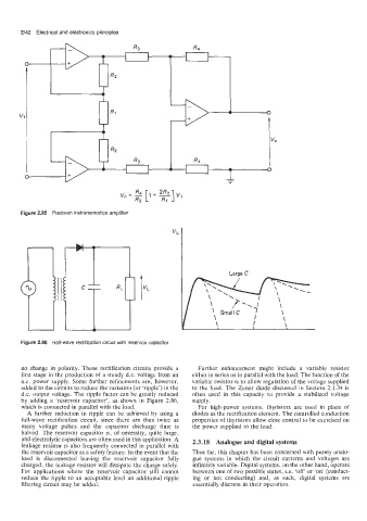
Figure 2.86 Half-wave rectification circuit with reservoir capacitor
no change in polarity. These rectification circuits provide a Further enhancement might include a variable resistor
first stage in the production of a steady d.c. voltage from an either in series or in parallel with the load. The function of the
a.c. power supply. Some further refinements are, however, variable resistor is to allow regulation of the voltage supplied
added to the circuits to reduce the variation (or ‘ripple’) in the to the load. The Zener diode discussed in Section 2.1.34 is
d.c. output voltage. The ripple factor can be greatly reduced often used in this capacity to provide a stabilized voltage
by adding a ‘reservoir capacitor’, as shown in Figure 2.86, supply.
which is connected in parallel with the load. For high-power systems, thyristors are used in place of
A further reduction in ripple can be achieved by using a diodes as the rectification element. The controlled conduction
full-wave rectification circuit, since there are then twice as properties of thyristors allow close control to be exercised on
many voltage pulses and the capacitor discharge time is the power supplied to the load.
halved. The reservoir capacitor is, of necessity, quite large,
and electrolytic capacitors are often used in this application. A 2.3.18 Analogue and digital systems
leakage resistor is also frequently connected in parallel with
the reservoir capacitor as a safety feature. In the event that the Thus far, this chapter has been concerned with purely analo-
load is disconnected leaving the reservoir capacitor fully gue systems in which the circuit currents and voltages are
charged, the leakage resistor will dissipate the charge safely. infinitely variable. Digital systems, on the other hand, operate
For applications where the reservoir capacitor still cannot between one of two possible states, i.e. ‘off‘ or ‘on’ (conduct-
reduce the ripple to an acceptable level an additional ripple ing or not conducting) and, as such, digital systems are
filtering circuit may be added. essentially discrete in their operation.