
Page 96 - Mechanical Engineers Reference Book
P. 96
Analogue and digital electronics theory 2/37
is no microelectronic equivalent for an inductor, but most 2.3.8 The triac
circuit designs can generally avoid the requirement for coiled The triac (or bidirectional thyristor) is similar in operation to
inductive elements. the thyristor but differs in that it can be switched into
When the integrated circuit is complete it is usually encapsu-
lated as a ‘dual-in-line’ (DIL) package. This is the normal conduction in either direction. In essence. the triac is equiva-
lent to two thyristors mounted back to back. Triacs find
form in which the integrated circuit is sold. An eight-pin DIL
package may contain a relatively simple circuit, but a 40-pin application to switching in full-wave alternating power
supplies.
DIL could easily contain all the electronics associated with a
central processing unit (CPU) for a computer system. These
latter devices contain a very large number of transistors and 2.3.9 Amplifiers
diodes (approaching 10 000 on a chip of less than 10 mm In general, electronic amplifiers are supplied with energy from
square). ‘The technology to produce this density of integration
is commonly called ‘very large-scale integration’. or VLSI. a d.c. source. An input signal to the circuit controls the
transfer of energy to the output, and the output signal should
be a higher-power version of that supplied to the input. The
2.3.7 The thyristor amplifier does not, however, function as some magical source
of free energy. The increased power across the amplifier is
Both the bipolar transistor and the FET can be utilized for
switching operations. These devices, however. are usually invariably drawn from the supply.
associatesd with low-power switching. For switching very large The term ‘amplifier’ is actually a shortened form for the
currents and voltages a speciai device called a ‘thyristor’ complete specification ‘voltage amplifier’. This has transpired
(formerly known as a silicon-controlled rectifier, SCR) is because most amplifiers are intended to magnify voltage
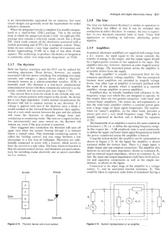
normally used. The thyristor is a four-layer. unidirectional levels. Any other type of amplifier is normally prefixed with
semiconductor device with three connections referred to as the the name of the quantity which is amplified (e.g. current
anode, cathode and the control gate (see Figure 2.74). amplifier. charge amplifier or power amplifier).
The current flow is from the anode to the cathode only and, Amplifiers may be broadly classified with reference to the
with the cathode positive with respect to the anode: the device frequency range over which they are designed to operate. In
has a very high impedance. Under normal circumstances the this respect there are two general categories: ‘wide-band’ and
thyristor will fail to conduct current in any direction. If a ‘narrow-band’ amplifiers. The names are self-explanatory in
voltage is applied such that if the thyristor were a diode it that the wide-band amplifier exhibits a constant power gain
would conduct in the forward-biased direction, then applica- over a large range of input signal frequencies. The narrow-
tion of a very small current between the gate and the cathode band (or ‘tuned’) amplifier, on the other hand: provides a
will cause the thyristor to abruptly change from non- power gain over a very small frequency range. This gain is
conducting to conducting mode. The turn-on is rapid (within a usually expressed in decibels and is defined by equation
few microseconds) and, once turned on, the thyristor will (2.58).
remain on, even if the gate current is removed. The bandwidth of an amplifier is used in the same context as
Once triggered into conduction the thyristor will turn off in Section 2.1.29, i.e. to define the operating frequency range.
again only when the current flowing through it is reduced In this respect the -3 dB amplitude ratio is used consistently
below a critical value. This minimum conducting current is to define the upper and lower input signal frequencies at which
called thl: ‘holding current’ and may range between a few the power transferred across the amplifier is halved.
microamps to a few tens of milliamps. Thyristors are addi- Using the system model, the arrplifier can be represented as
tionally connected in series with a resistor, which serves to shown in Figure 2.75. In the figure the amplifier is shown
limit the current to a safe value. The basic thyristor function is enclosed within the broken lines. There is a single input, a
that of a power-control device, and thyristors are used extens- single output and one common connection. The amplifier also
ively for switching mains electricity and as speed controllers features an internal input impedance, shown as resistance Ri;
for d.c. motors. and an internal output impedance, shown as resistance R,. In
fact, the input and output impedances could have both induct-
ive and capacitive components as well as the simple res-
istances, as shown in the figure.
Connected to the input stage of the amplifier is a voltage
source, V,, and its associated internal resistance, R,. This
Anode Anode could be taken to represent some form of transducer having a
- -------
r-----
I I
Gate
‘I
L _____----
Cathode Cathode I’ --J
Figure 2.74 Thyristor device and circuit symbol Figure 2.75 System representation of an amplifier