
Page 91 - Mechanical Engineers Reference Book
P. 91
2/32 Electrical and electronics principles
which the calculation is to be based. The transformation ratio
is used to scale the equivalent values. For example, the copper
loss on the secondary side, 12R2, can be referred to the
primary side through the relation
(2.93)
where the prime denotes the referred values. Using equation
(2.90) the referred resistance becomes
Ri = {NllNz}2R, (2.94)
Thus equation (2.94) gives an equivalent resistance, Ri, in the
primary side which accounts for the actual resistance, Rz, of
the secondary winding. Reactances may be similarly referred
to one or other side of the transformer for calculation pur-
poses.
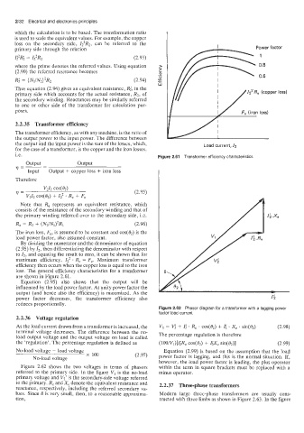
2.2.35 Transformer efficiency
The transformer efficiency, as with any machine, is the ratio of
the output power to the input power. The difference between
the output and the input power is the sum of the losses, which, Load current, 12
for the case of a transformer, is the copper and the iron losses,
i.e. Figure 2.61 Transformer efficiency characteristics
output output
9=-- -
Input Output + copper loss + iron loss
Therefore
(2.95)
Note that Re represents an equivalent resistance, which
consists of the resistance of the secondary winding and that of
the primary winding referred over to the secondary side, Le.
Re = R2 + (NZ/Nl)’R1 (2.96)
The iron loss, F,, is assumed to be constant and cos(&) is the
load power factor, also assumed constant.
By dividing the numerator and the denominator of equation
(2.95) by 12, then differentiating the denominator with respect
to 12, and equating the result to zero, it can be shown that for
maximum efficiency, 12 . Re = F,. Maximum transformer
efficiency then occurs when the copper loss is equal to the iron
loss. The general efficiency characteristics for a transformer
are shown in Figure 2.61.
Equation (2.95) also shows that the output will be
influenced by the load power factor. At unity power factor the
output (and hence also the efficiency) is maximized. As the
power factor decreases, the transformer efficiency also
reduces proportionally.
Figure 2.62 Phasor diagram for a transformer with a lagging power
factor load current
2.2.36 Voltage regulation
As the load current drawn from a transformer is increased, the VI = Vi + I; . Re . cos(&) + I; . Xe . sin(Oz) (2.98)
terminal voltage decreases. The difference between the no- The percentage regulation is therefore
load output voltage and the output voltage on load is called
the ‘regulation’. The percentage regulation is defined as (lOO/Vl)[I;R, cos(02) + IiX, sin(tIz)] (2.99)
No-load voltage - load voltage Equation (2.99) is based on the assumption that the load
No-load voltage x 100 (2.97) power factor is lagging, and this is the normal situation. If,
however, the load power factor is leading, the plus operator
Figure 2.62 shows the two voltages in terms of phasors within the term in square brackets must be replaced with a
referred to the primary side. In the figure VI is the no-load minus operator.
primary voltage and V,’ is the secondary-side voltage referred
to the primary. R, and X, denote the equivalent resistance and 2.2.37 Three-phase transformers
reactance, respectively, including the referred secondary va-
lues. Since 6 is very small, then, to a reasonable approxima- Modern large three-phase transformers are usually cons-
tion, tructed with three limbs as shown in Figure 2.63. In the figure