
Page 87 - Mechanical Engineers Reference Book
P. 87
2/28 Electrical and electronics principles
2.2.24.4 Reduced stator voltage Sau irrel-caae
By reducing the applied stator voltage a family of tor-
que-speed characteristics are obtained, as shown in Figure
2.53. It is evident that as the stator voltage is reduced from VI
to V,, a change in speed is effected at any particular value of
torque. This is provided, of course, that the torque does not
exceed the maximum load torque available at the reduced
stator voltage. This latter point is obviously a limiting factor
which places a constraint on this method of speed control.
Generally, only very small speed ranges can be obtained using
a variable stator supply voltage.
2.2.25 Single-phase induction motors
The operation of an induction motor depends upon the /
creation of a rotating magnetic field. A single stator coil Single-phase
cannot achieve this, and all the so-called single-phase induc- winding
tion motors use some or other external means of generating an
approximation to a two-phase stator supply. Two stator coils Figure 2.54 Shaded pole motor
are therefore used and these are displaced by 90". Ideally, the
currents which supply each coil should have a phase difference
of 90". This then gives the two-phase equivalent of the
three-phase induction motor. A.C. supply
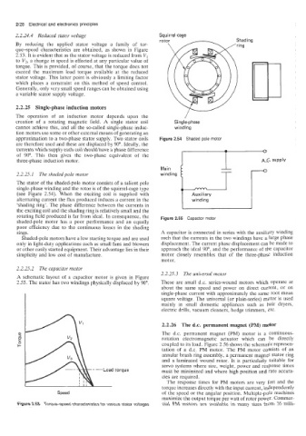
2.2.25.1 The shaded-pole motor winding
The stator of the shaded-pole motor consists of a salient pole i
single-phase winding and the rotor is of the squirrel-cage type
(see Figure 2.54). When the exciting coil is supplied with Auxiliary
alternating current the flux produced induces a current in the winding
'shading ring'. The phase difference between the currents in
the exciting coil and the shading ring is relatively small and the
rotating field produced is far from ideal. In consequence, the Figure 2.55 Capactor motor
shaded-pole motor has a poor performance and an equally
poor efficiency due to the continuous losses in the shading
rings. A capacitor is connected in series with the auxiliary winding
Shaded-pole motors have a low starting torque and are used such that the currents in the two windings have a large phase
only in light-duty applications such as small fans and blowers displacement. The current phase displacement can be made to
or other easily started equipment. Their advantage lies in their approach the ideal 90", and the performance of the capacitor
simplicity and low cost of manufacture. motor closely resembles that of the three-phase induction
motor.
2.2.25.2 The capacitor motor
2.2.25.3 The universal motor
A schematic layout of a capacitor motor is given in Figure
2.55. The stator has two windings physically displaced by 90". These are small d.c. series-wound motors which operate at
about the same speed and power on direct current, or on
single-phase current with approximately the same root mean
square voltage. The universal (or plain-series) motor is used
mainly in small domestic appliances such as hair dryers,
electric drills, vacuum cleaners, hedge trimmers, etc.
2.2.26 The d.c. permanent magnet (PM) motor
The d.c. permanent magnet (PM) motor is a continuous-
rotation electromagnetic actuator which can be directly
coupled to its load. Figure 2.56 shows the schematic represen-
tation of a d.c. PM motor. The PM motor consists of an
annular brush ring assembly, a permanent magnet stator ring
and a laminated wound rotor. It is particularly suitable for
servo systems where size, weight, power and response times
torque must be minimized and where high position and rate accura-
cies are required.
The response times for PM motors are very fast and the
torque increases directly with the input current, independently
Speed of the speed or the angular position. Multiple-pole machines
maximize the output torque per watt of rotor power. Commer-
Figure 2.53 Torque-speed characteristics for various stator voltages cial PM motors are available in many sizes from 35 milli-