
Page 86 - Mechanical Engineers Reference Book
P. 86
--
Electrical machines 2127
Three-phase supply 2.2.24.1 Change of supply current frequency
Solid state variable-frequency drives first began to appear in
1968. They were originally applied to the control of synchro-
nous a.c. motors in the synthetic fibre industry and rapidly
---- gained acceptance in that particular market. In more recent
times they have been used in applications such as pumping,
1
I
synchronized press lines, conveyor lines and, to a lesser
extent, in the machine-tool industry as spindle drives. Modern
a.c. variable-frequency motors are available in power ratings
ranging from 1 kW to 750 kW and with speed ranges from l0il
to 10011.
2.2.24.2 Change of number of poles
By bringing out the ends of the stator coils to a specially
designed switch it becomes possible to change an induction
motor from one pole configuration to another. To obtain three
different pole numbers, and hence three different speeds, a
fairly complex switching device would be required.
Changing the number of poles gives a discrete change in
I motor speed, with little variation in speed over the switched
I range. For many applications, however, two discrete speeds
1 Start are all that is required and changing the number of poles is a
simple and effective method of achieving this.
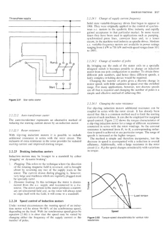
Figure 2.51 Stardelta starter
2.2.24.3 Changing the rotor resistance
For slip-ring induction motors additional resistance can be
coupled in series with the rotor circuit. It has already been
2.2.22.2 Auto-transformer starter stated that this is a common method used to limit the starting
current of such machines. It can also be employed for marginal
The aulo-transformer represents an alternative method of speed control. Figure 2.52 shows the torque characteristics of
reducing the starting current drawn by an induction motor. a slip-ring induction motor for a range of different resistances
connected in series with the rotor windings. As the external
2.2.22.3 Rotor resistance resistance is increased from R1 to R3 a corresponding reduc-
tion in speed is achieved at any particular torque. The range of
With slip-ring induction motors it is possible to include speeds is increased at the higher torques.
additional resistance in series with the rotor circuit. The The method is simple and therefore inexpensive, but the
inclusion of extra resistance in the rotor provides for reduced decrease in speed is accompanied with a reduction in overall
starting current and improved starting torque. efficiency. Additionally, with a large resistance in the rotor
circuit (i.e. R3) the speed changes considerably with variations
2.2.23 Braking induction motors in torque.
Induction motors may be brought to a standstill by either
’p!ugging’ or dynamic braking’:
1. Plugging: This refers to the technique where the direction
of the rotating magnetic field is reversed, and is brought
about by reversing any two of the supply leads to the
stator. The current drawn during plugging is, however,
very large and machines which are regularly plugged must
be specially rated.
2. Dynamic braking: In this technique the stator is discon-
nected from the a.c. supply and reconnected to a d.c.
source. The direct current in the stator produces a station-
ary unidirectional field and, as the rotor will always tend
to align itself with the field, it will come to a standstill.
2.2.24 Speed control of induction motors
Under normal circumstances the running speed of an induc-
tion motor will be about 9498% of the synchronous speed,
depending on the load. With the synchronous speed given by Speed
equation (2.80) it is clear that the speed may be varied by
changing either the frequency of the supply current or the Figure 2.52 Torque-speed characteristics for various rotor
number of poles. resistances