
Page 89 - Mechanical Engineers Reference Book
P. 89
2/30 Electrical and electronics principles
r-7
Phase
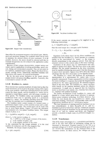
Figure 2.59 Two-phase brushless motor
Max
pu ll-ou t
If the motor currents are arranged to be supplied in the
Max Frequency following relationships:
puli-in (step&)
rate (speed) IA = I sin(pOI2) and IB = I cos@8/2)
then the total torque for a two-pole motor becomes
Figure 2.58 Stepper motor characteristics
T = TA + TB = /KT[Sin2(@) + COS2(@)]
= IKT (2.85)
than either the permanent magnet or the hybrid types. Mecha-
nical and electronic dampers are available which can be used Equation (2.85) shows that if all the above conditions are
to minimize the adverse effects of rotor resonance. If at all satisfied then the brushless d.c. motor operates in a manner
possible, however, the motor should be selected such that its similar to the conventional d.c. motor, i.e. the torque is
resonant frequencies are not critical to the application under directly proportional to the armature current. Note that the
consideration. armature current in this context refers to the stator windings.
Because of their unique characteristics, stepper motors are Excitation of the phases may be implemented with sinu-
widely used in applications involving positioning, speed con- soidal or square-wave inputs. The sine-wave drive is the most
trol, timing and synchronized actuation. They are prevalent in efficient, but the output transistors in the drive electronics
X-Y plotters, punched-taped readers, floppy disc head drives, must be capable of dissipating more power than that dissipated
printer carriage drives, numerically controlled machine tool in square-wave operation. Square-wave drive offers the added
slide drives and camera iris control mechanisms. advantage that the drive electronics can be digitally based.
By far the most severe limitation on the purely electric The brushless d.c. motor will duplicate the performance
stepper motor is its power-handling capability. Currently, this characteristics of a conventional d.c. motor only if it is
is restricted to about 2.25 kW. properly commutated. Proper commutation involves exciting
the stator windings in a sequence that keeps the magnetic field
produced by the stator approximately 90 electrical degrees
2.2.28 Brushless d.c. motors ahead of the rotor field. The brushless d.c. motor therefore
These motors have position feedback of some kind so that the relies heavily on the position feedback system for effective
input waveforms can be kept in the proper timing with respect commutation. It might also be apparent that the brushless
to the rotor position. Solid-state switching devices are used to motor as described is not strictly a d.c. machine but a form of
control the input signals, and the brushless d.c. motor can be a.c. machine with position feedback.
operated at much higher speeds, with full torque available at The further development of the brushless d.c. motor will
those speeds. The brushless motor can normally be rapidly depend to a large extent upon future advances in semicon-
accelerated from zero to operating speed as a permanent ductor power transistor technology. It is likely, however, that
magnet d.c. motor. On reaching operating speed the motor within the next decade the true brushless d.c. motor, using
can then be switched over to synchronous operation. solid-state swiching, will become commercially viable and will
The brushless motor system consists of a wound stator, a progressively dominate the d.c. servosystem market.
permanent magnet rotor, a rotor position sensor and a solid- This brief discussion of rotating electrical machines is in no
state switching assembly. The wound stator can be made with way comprehensive. A fuller discourse on ax. and d.c.
two or more input phases. Figure 2.59 gives the schematic machines is given by both Gray4 and Sen.’ Orthweid presents
representation of a two-phase brushless motor. The torque an interesting practical discussion on the mechanical applica-
output of phase A is tions of a.c. and d.c. motors and Kenjo and Nagamori7
provide a detailed in-depth study of permanent-magnet d.c.
TA = Z~(Z@l2r) sin(pOl2) = IAKT sin@@/2) (2.83) motors.
where /A is the current in phase A,
KT = (Z@/2r), is the torque constant of the motor, 2.2.29 Transformers
p is the number of poles, and One of the major advantages of a.c. transmission and distribu-
0 is the angular position of the rotor.
In the expression for the torque constant; Z is the total tion is the ease with which an alternating voltage can be
number of conductors and @ is the magnetic flux. increased or decreased. Common practice in the UK is to
Similarly, the torque output of phase B is generate voltages at 11-22 kV and then transform up to 33 kV
(or 132 kV) for transmission on the National Grid to the
TB = IBKT COS(^%/^) (2.84) consumer centres. At these centres, the voltages are trans-