
Page 90 - Mechanical Engineers Reference Book
P. 90
Electrical machines 2/31
formed lback down to 415 V (or 240 V) and then distributed 2.2.31 Transformer voltage equation
for industrial and domestic use.
In normal operation the flux may be considered to be a
sinusoidally varying quantity, i.e.
2.2.30 Basic transformer action
4 = @ sin(wt) (2.91)
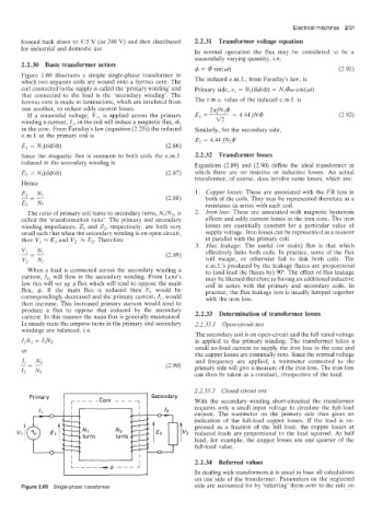
Figure ;!.60 illustrates a simple single-phase transformer in
which two separate coils are wound onto a ferrous core. The The induced e.m.f., from Faraday’s law, is
coii connected to the supply is called the ‘primary winding’ and Primary side, el = N,(d+/dt) = N1@w cos(ot)
that connected to the load is the ‘secondary winding’. The
ferrous core is made in laminations, which are insulated from The r.m.s. value of the induced e.m.f. is
one another, to reduce eddy current losses. 2~ifN1@
If a sinusoidal voltage, VI, is applied across the primary El = __ = 4.44 fN@ (2.92)
winding a current, I,, in the coil will induce a magnetic flux, 6, v2
in the core. From Faraday’s law (equation (2.25)) the induced Similarly, for the secondary side,
e.m.f. in the primary coil is
E2 = 4.44 fN2@
El = Nl(d@dt) (2.86)
Since the magnetic flux is common to both coils the e.m.f. 2.2.32 Transformer losses
induced in the secondary winding is Equations (2.89) and (2.90) define the ideal transformer in
(2.87) which there are no resistive or inductive losses. An actual
transformer, of course, does involve some losses, which are:
1. Copper losses: These are associated with the 12R loss in
(2.88) both of the coils. They may be represented therefore as a
resistance in series with eacb coil.
The ratio of primary coil turns to secondary turns, Nl/N2, is 2. Iron loss: These are associated with magnetic hysteresis
cailed the ‘transformation ratio’. The primary and secondary effects and eddy current losses in the iron core. The iron
winding impedances, Z1 and Z,; respectively, are both very losses are essentially constant for a particular value of
small such that when the secondary winding is on open circuit, supply voltage. Iron losses can be represented as a resistor
then VI = El and V2 = E2. Therefore in parallel with the primary coil.
3. Flux leakage: The useful (or main) flux is that which
effectively links both coils. In practice, some of the flux
(2.89)
will escape, or otherwise fail to link both coils. The
e.m.f.’s produced by the leakage fluxes are proportional
When a load is connected across the secondary winding a to (and lead the fluxes by) 90”. The effect of flux leakage
current, 12, will flow in the secondary winding. From Lenz’s may be likened therefore to having an additional inductive
law this will set up a flux which will tend to oppose the main coil in series with the primary and secondary coils. In
flux, 4. If the main flux is reduced then El would be practice, the flux leakage loss is usually lumped together
correspondingly decreased and the primary current, 11, would with the iron loss.
then increase. This increased primary current would tend to
produce a flux to oppose that induced by the secondary
current. In this manner the main flux is generally maintained. 2*2*33 Determination Of lransformer losses
In steady state the ampere-turns in the primary and secondary 2.2.33.1 Open-circuit test
windings are balanced, i.e.
The secondary coil is on open-circuit and the full-rated voltage
I1Nl = IzN2 is applied to the primary winding. The transformer takes a
or small no-load current to supply the iron loss in the core and
the copper losses are essentially zero. Since the normal voltage
and frequency are applied, a wattmeter connected to the
(2.90) primary side will give a measure of the iron loss. The iron loss
can then be taken as a constant, irrespective of the load.
2.2.33.2 Closed-circuit test
With the secondary winding short-circuited the transformer
requires only a small input voltage to circulate the full-load
current. The wattmeter on the primary side then gives an
I “2 pressed as a fraction of the full load, the copper losses at
indication of the full-load copper losses. If the load is ex-
reduced loads are proportional to the load squared. At half
load, for example, the copper losses are one quarter of the
full-load value.
2.2.34 Referred values
In dealing with transformers it is usual to base all calculations
on one side of the transformer. Parameters on the neglected
Figure 2.60 Single-phase transformer side are accounted for by ‘referring’ them over to the side on