
Page 88 - Mechanical Engineers Reference Book
P. 88
Electrical machines 2/29
Stator I
F\
Figure 2.56 D.C. permanent magnet motor
Newton-metres at about 25 mm diameter to 13.5 Newton-
metres at about 3 m diameter.
Direct-drive rate and position systems using PM motors
utilize d.c. tachogenerators and position sensors in various
forms of closed-ioop feedback paths for control purposes.
2.2.27 The stepper motor
A stepper motor is a device which converts a d.c. voltage pulse
train into a proportional mechanical rotation of its shaft. The
slepper motor thus functions both as an actuator and as a
position1 transducer. The discrete motion of the stepper motor -Y
makes it ideally suited for use with a digitally based control
system :such as a microcomputer.
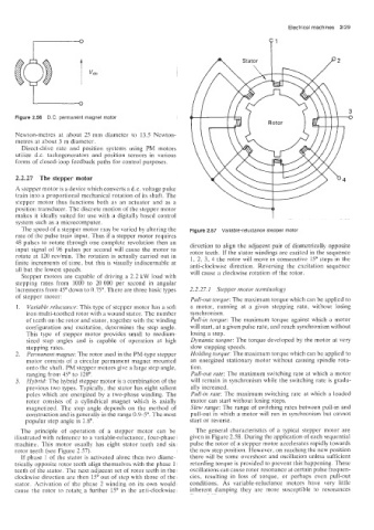
The speed of a stepper motor may be varied by altering the Figure 2.57 Variable-reluctance stepper motor
rate of i.he pulse train input. Thus if a stepper motor requires
48 pulses to rotate through one complete revolution then an direction to align the adjacent pair of diametrically opposite
input signal of 96 pulses per second will cause the motor to rotor teeth. If the stator windings are excited in the sequence
rotate at 120 revimin. The rotation is actually carried out in 1, 2. 3, 4 the rotor will move in consecutive 15" steps in the
finite increments of time, but this is visually indiscernable at anti-clockwise direction. Reversing the excitation sequence
all but the lowest speeds. will cause a clockwise rotation of the rotor.
Stepper motors are capable of driving a 2.2 kW load with
stepping rates from 1000 to 20 000 per second in angular
ncrements from 45" down to 0.75". There are three basic types 2.2.27.1 Stepper motor terminology
of stepper motor:
Pull-out torque: The maximum torque which can be applied to
Variable reluctance: This type of stepper motor has a soft a motor, running at a given stepping rate; without losing
iron1 multi-toothed rotor with a wound stator. The number synchronism.
of teeth on the rotor and stator, together with the winding Pull-in torque: The maximum torque against which a motor
configuration and excitation, determines the step angle. will start, at a given pulse rate, and reach synchronism without
This type of stepper motor provides small to medium- losing a step.
sized step angles and is capable of operation at high Dynamic torque: The torque developed by the motor at very
stepping rates. slow stepping speeds.
Permanent magnet: The rotor used in the PM-type stepper Holding torque: The maximum torque which can be applied to
motor consists of a circular permanent magnet mounted an energized stationary motor without causing spindle rota-
onto the shaft. PM stepper motors give a large step angle, tion.
ranging from 45" to 120". Pull-out rate: The maximum switching rate at which a motor
Hybrid: The hybrid stepper motor is a combination of the will remain in synchronism while the switching rate is gradu-
previous two types. Typically, the stator has eight salient ally increased.
poles which are energized by a two-phase winding. The Pull-in rate: The maximum switching rate at which a loaded
rotor consists of a cylindrical magnet which is axially motor can start without losing steps.
magnetized. The step angle depends on the method of Slew range: The range of switching rates between pull-in and
construction and is generally in the range 0.9-5". The most pull-out in which a motor will run in synchronism but cannot
popular step angle is 1.8". start or reverse.
The principle of operation of a stepper motor can be The general characteristics of a typical stepper motor are
illustrated with reference to a variable-reluctance, four-phase given in Figure 2.58. During the application of each sequential
machifit.. This motor usually has eight stator teeth and six pulse the rotor of a stepper motor accelerates rapidly towards
rotor teeth (see Figure 2.57). the new step position. However, on reaching the new position
If phase 1 of the stator is activated alone then two diame- there will be some overshoot and oscillation unless sufficient
trically opposite rotor teeth align themselves with the phase 1 retarding torque is provided to prevent this happening. These
teeth of the stator. The next adjacent set of rotor teeth in the oscillations can cause rotor resonance at certain pulse frequen-
clockwise direction are then 15" out of step with those of the cies, resulting in loss of torque, or perhaps even pull-out
stator. Activation of the phase 2 winding on its own would conditions. As variable-reluctance motors have very little
cause the rotor to rotate a further 15" in the anti-clockwise inherent damping they are more susceptible to resonances