
Page 83 - Mechanical Engineers Reference Book
P. 83
2/24 Electrical and electronics principles
To load
Star
Figure 2.44 Star and delta connections for three-phase systems
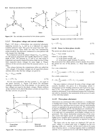
Figure 2.46 Alternator windings in delta connection
2.2.17 Three-phase voltage and current relations
Figure 2.45 shows a three-phase star connected alternator IL = mx Ip (2.77)
supplying currents IR, Iy and ZB to a balanced (or equal)
resistive-inductive load. This gives the usual 'four-wire' star- 2.2.18 Power in three-phase circuits
connected system. Since there are only four transmission
cables involved, the alternator connected in a star pattern will The power per phase is given by
only require four slip-rings. Pphase = vPzP cos(+) (2.78)
For a balanced system the phase voltages V,,, V,, and VBN
are all equal in magnitude and equally displaced by a phase where Vp is the phase voltage,
angle of 120". The currents IR, Zy and ZB are also equal in Zp is the phase current, and
magnitude and equally displaced in phase angle but they all lag + is the phase angle between Vp and I,.
their respective phase voltages by some angle +. Phasor The total power for a three-phase circuit is simply three times
addition of the currents shows that the neutral current, Z,, is the power for one of the phases, Le. three times equation
zero. (2.78).
The voltages between the transmission cables are called the For a star connection:
'line' voltages. If the phase voltages are all equal then phasor
addition shows that the line voltages are given by VL
P 1 - COS(+) = V'TX VL X ZL COS(+) (2.79)
3
IL
vl~ne = 2Vphase c0s(30) v3
or For a delta connection:
VL = m x v, (2.76) P = 3vL- IL cos(+) = VTX v, x z, cos(4)
For the star connection, the line currents, ZL, are equal to v3
the phase currents, Ip. Figure 2.46 shows the alternator The same relation is obtained. In terms of line voltages and
windings connected in the delta pattern. In this pattern the currents therefore, the power in a three-phase circuit is
line voltages are equal to the phase voltages. Phasor addition independent of the winding connection and is given by equa-
of the currents shows that if the phase currents are equal then tion (2.79). This equation does not, however, apply if the
the line currents are given by system is unbalanced. In an unbalanced system the total power
can only be obtained as the summation of the powers in each
of the individual phases.
R
2.2.19 Three-phase alternators
Alternators are constructed with a stationary a.c. winding and
Neutral wire a rotating field system. This reduces the number of slip-rings
required to two, and these have to carry only the field-exciting
current as opposed to the generated current. The construction
is thereby simplified and the slip-ring losses are minimized. In
addition, the simpler arrangement enables heavier insulation
to be used and, in consequence, much higher voltages can be
generated. The robust mechanical construction of the rotor
also means that higher speeds are possible and substantially
higher power outputs can be generated with an alternator. A
simple form of three-phase generator is depicted in Figure
2.47.
The three coils on the stator are displaced 120" and the
Three-phase Balanced rotor, which is a salient pole type, is supplied via the two
alternator three-phase load slip-rings with a d.c. current. As the rotor is driven by some
form of prime mover, a rotating magnetic field is established
Figure 2.45 Three-phase supply connections and the e.m.f.'s generated in the coils will be displaced with a