
Page 78 - Mechanical Engineers Reference Book
P. 78
Electrical machines 211 9
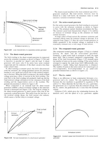
The shunt-wound machine is the most common type of d.c.
generator employed. The load current, however, must be
limited to a value well below rhe maximum value to avoid
excessive variation in terminal voltage.
Open-circuit voltage
a,
a, 2.2.5 The series-wound generator
OI
OI
+
+
I
I
0 For the series-wound generator the field winding is connected
0
-
- Separately in series with the armature terminals as shown in Figure
Separately
m
m
._ excited 2.27(c). The armature current therefore determines the flux.
excited
E generator The constant speed load characteristic (Figure 2.31) exhibits
generator
an increase in terminal voltage as the armature (or load)
\ current increases.
\ At large values of load current the armature resistance and
Shunt-wound reactance effects cause the terminal voltage to decrease. It is
I generator apparent from Figure 2.31 that the series-wound generator is
I totally unsuitable if the terminal voltage is required to be
reasonably constant over a wide range of load current.
Armature current, I,
2.2.6 The compound-wound generator
Figure 2.29 Load characteristic of a separately excited generator
The compound-wound generator (Figure 2.27(d)) is a hybrid
2.2.4 The s~~nt-wound generator between the shunt- and the series-wound generators.
Normally. a small series field is arranged to assist the main
The field winding in the shunt-wound generator is connected shunt field. This is termed ‘cumulative compounding’. The
across the armature terminals as shown in Figure 2.27(b) and shape of the load characteristic (Figure 2.32) depends upon
is therefore in parallel (or ’shunt’) with the load. A shunt the number of turns on the series winding. If the series field is
generator will excite only if the poles have some residual arranged to oppose the main shunt field (‘differentially com-
magnetism and the resistance of the shunt circuit is less than pounded’) a rapidly falling load characteristic is obtained.
some critical value. The number of turns on the series coil can be varied to give an
If, when running at constant speed, the field is disconnected over-compounded, level-compounded or an under-com-
from the armature, the voltage generated across the armature pounded characteristic as shown in Figure 2.32.
brushes is very small and entirely due to the residual magnet-
ism in the iron. When the field is connected, the small residual 2.2.7 The d.c. motor
voltage generates a flow of current in the field winding. The
total flux in the field winding will gradually build up and the There is no difference in basic construction between a d.c.
final terminal voltage will depend on the resistance of the field generator and a d.c. motor. The only significant distinction
winding and the magnetization curve of the machine. The between the two machines is quantified by equations (2.70)
general characteristic is shown in Figure 2.30. and (2.71). These illustrate the fact that, for a d.c. generator,
When connected to an external load the shunt-wound the generated e.m.f. is greater than the terminal voltage. For
generator exhibits a drop in terminal voltage as the armature the d.c. motor, the generated e.m.f. is less than the terminal
current is increased (see Figure 2.29). The drop in voltage in voltage.
the shunt-wound generator is much greater than that in the Equation (2.65), which gives the relationship between the
separately excited generator. This stems from the fact that, as induced e.m.f. and the speed of a d.c. generator, applies
the termiiial voltage drops, the field current also reduces,
which causes a further drop in terminal voltage.
Final no-load
---
voltage
Armature current
Field current, 1,
Figure 2.31 Constant speed load characteristic for the series-wound
Figure 2.30 No-load characteristic of a shunt-wound generator generator