
Page 76 - Mechanical Engineers Reference Book
P. 76
Electrical machines 2/17
I 2.2.1.2 Armature torque
The force on a current-carrying conductor is given by equation
(2.27). i.e.
F = BlI
Outpui:
voltage The torque on one armature conductor is therefore
T = Fr = BavlIar (2.68)
where r is the radius of the armature conductor about the
centre of rotation,
0 180 360 I, is the current flowing in the armature conductor
I is the axial length of the conductor, and
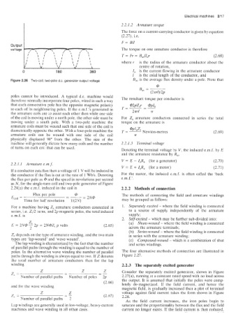
Figure 2.26 Two-coil. twopole d.c. generator output voltage B,, is the average flux density under a pole. Note that
dl
(27rr1)/2p
B,, = ~
poles cannot be introduced. A typical d.c. machine would
therefore normally incorporate four poles, wired in such a way The resultant torque per conductor is
that each consecutive pole has the opposite magnetic polarity T=L-- @pia
@2plI
r
to each of its neighbouring poles. If the e.m.f.’s generated in -
the armature coils are to assist each other then while one side 2nd 7~
of the coil is moving under a north pole, the other side must be For Z, armature conductors connected in series the total
moving under a south pole. With a two-pole machine the torque on the armature is
armature coils must be wound such that one side of the coil is
diametrically opposite the other. With a four-pole machine the T=- @PIaZs Newton-metres (2.69)
armature coils can be wound with one side of the coil 7r
physically displaced 90” from the other. The size of the
machine will generally dictate how many coils and the number 2.2.1.3 Terminal voltage
of turns on each coil that can be used.
Denoting the terminal voltage hy V, the induced e.m.f. by E
and the armature resistance by R,,
V = E - IaRa (for a generator) (2.70)
2.2.1.1 Armature e.m.f.
V = E + I,R, (for a motor) (2.71)
If a coiiductor cuts flux then a voltage of 1 V will be induced in
the conductor if the flux is cut at the rate of 1 Wbis. Denoting For the motor, the induced e.m.f. is often called the ‘back
the flux per pole as @ and the speed in revolutions per second e.m.f.’.
as N, for the single-turn coil and two-pole generator of Figure
2.24(al the e.m.f. indcced in the coil is 2.2.2 Methods of connection
Flux per pole aj The methods of connecting the field and armature windings
EmI = - - 2N@
Time for half revolution 1/(2N) may be grouped as follows:
For a machine having Z, armature conductors connected in 1. Separately excited - where the field winding is connected
series, i.e. 242 turns, and 2p magnetic poles, the total induced to a source of supply independently of the armature
e.m.f. is supply;
2. Self-excited - which may be further sub-divided into:
2 (a) Shunt-wound - where the field winding is connected
E = 2!V@ 2p = 2N@Z, p volts (2.65)
2 across the armature terminals;
(b) Series-wound - where the field winding is connected
Zs depends on the type of armature winding, and the two main in series with the armature winding;
types are ‘lap-wound’ and wave-wound’. (c) Compound-wound - which is a combination of shut
The lap winding is characterized by the fact that the number and series windings.
of para.lle1 paths through the winding is equal to the number of
poles. In the alternative wave winding the number of parallel The four alternative methods of connection are illustrated in
paths through the winding is always equal to two. If 2 denotes Figure 2.27.
the total number of armature conductors then for the lap
winding 2.2.3 The separately excited generator
Z Z Z Consider the separately excited generator, shown in Figure
-
=- - -_
-
I Number of parallel paths Number of poles 2p 2.27(a), running at a constant rated speed with no load across
the output. It is assumed that initially the poles were comp-
(2.66)
and for the wave winding letely de-magnetized. If the field current, and hence the
magnetic field, is gradually increased then a plot of terminal
Z
z, Z -_ (2.67) voltage against field current takes the form shown in Figure
-
=
Number of parallel paths 2 2.28.
As the field current increases, the iron poles begin to
Lap windings are generally used in low-voltage, heavy-current saturate and the proportionality between the flux and the field
machines and wave winding in all other cases. current no longer exists. If the field current is ?hen reduced.