
Page 71 - Mechanical Engineers Reference Book
P. 71
211 2 Electrical and electronics principles
-
power requirements from a common supply may be deter-
mined.
When quoting power factor in practical applications it is
usual to state the phase of the current with respect to the
voltage. For an inductive load the current lags the voltage and
the power factor is said to be lagging. For a predominantly
capacitive load the current leads the voltage and the power
factor is leading.
If the power is supplied from, say, an alternator rated at
400 V and 1000 A, then these are the highest voltage and
current that the machine can tolerate without overheating.
The phase difference between the voltage and current is
entirely dependent upon the load. Thus if the power factor of
the load is unity then the 400 kVA alternator can supply
400 kW of power to the load. Neglecting losses, the prime
mover which drives the alternator must also be capable of
supplying 400 kW. If, on the other hand, the power factor of
the load is 0.5. then the power supplied will only be 200 kW.
This means that although the generator will be operating at its
rated kVA, the prime mover which drives the genrator will be
Figure 2.16 Parallel RLC circuit operating at only half of its capacity.
An alternative way of looking at this phenomenon is to
2.1.28 Power and power factor in a.c. circuits consider a load of, say, 100 kW, with a lagging power factor of
0.75. If the supply voltage is 50 V, then the required current,
Denoting the phase an le between the voltage and the current from equation (2.55), is 2.67 A. If, however, the power factor
as 4, it may be shown 9 that the average power is
of the load were to be increased to unity, then the required
current would be reduced to 2 A. This means that the
vnl I,
Pa, = - - cos(+) conducting cables, in supplying a reduced current, may have a
1/2 v2 correspondingly reduced cross-sectional area.
In terms of r.m.s. values: In general, the size of an electrical system including trans-
mission lines, switchgear and transformers is dependent upon
Pa, = VI cos(+) (2.55) the size of the current. It is economically viable therefore to
ensure that the current is minimized. As a further incentive to
where cos(+) is called the ‘power factor’.
Power factor is an important parameter when dealing with industrial consumers, the electricity supply authorities
electrical transformers and generators. All such machines are normally operate a two-part tariff system. This consists of a
rated in terms of kilo-volt amperes (kVA), which is a measure fixed rate depending on the kVA rating of the maximum
of the current-carrying capacity for a given applied voltage. demand and a running charge per unit kilowatts consumed per
The power that can be drawn depends both on the kVA rating hour.
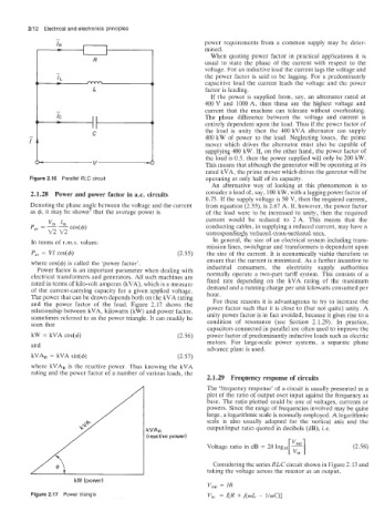
and the power factor of the load. Figure 2.17 shows the For these reasons it is advantageous to try to increase the
relationship between kVA, kilowatts (kW) and power factor. power factor such that it is close to (but not quite) unity. A
sometimes referred to as the power triangle. It can readily be unity power factor is in fact avoided, because it gives rise to a
seen that condition of resonance (see Section 2.1.29). In practice,
capacitors connected in parallel are often used to improve the
kW = kVA COS(^) (2.56) power factor of predominantly inductive loads such as electric
and motors. For large-scale power systems, a separate phase
advance plant is used.
kVAR = kVA sin(&) (2.57)
where kVAR is the reactive power. Thus knowing the kVA
rating and the power factor of a number of various loads, the
2.1.29 Frequency response of circuits
The ‘frequency response’ of a circuit is usually presented as a
plot of the ratio of output over input against the frequency as
base. The ratio plotted could be one of voltages, currents or
powers. Since the range of frequencies involved may be quite
large, a logarithmic scale is normally employed. A logarithmic
scale is also usually adopted for the vertical axis and the
outpnthnput ratio quoted in decibels (dB), i.e.
[?I]
Voltage ratio in dB = 20 loglo ~ (2.58)
Considering the series RLC circuit shown in Figure 2.13 and
taking the voltage across the resistor as an output,
kW (power)
V,,, = IR
Figure 2.17 Power triangle Vi, = Z[R + j(wL - l/oC)]