
Page 67 - Mechanical Engineers Reference Book
P. 67
2/8 Electrical and electronics principles
Figure 2.8 shows two such coils sharing a common magnetic Magnetic flux density
flux path in the form of a toroid. The mutual inductance B
between the two coils is
N24
(H)
M = - (2.33)
I1 A
where N2 is the number of turns on coil 2,
Il is the current through coil 1, and
4 is the magnetic flux linking coils 1 and 2.
The mutual inductance effect finds great application both to
electrical transformers and to rotating electrical machines.
Magnetic intensity
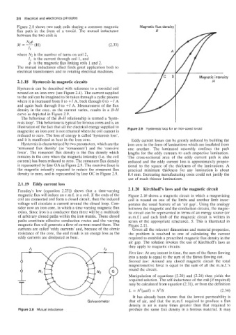
2.1.18 Hysteresis in magnetic circuits
Hysteresis can be described with reference to a toroidal coil
wound on an iron core (see Figure 2.4). The current supplied
to the coil can be imagined to be taken through a cyclic process
where it is increased from 0 to +I A, back through 0 to -I A
and again back through 0 to +I A. Measurement of the flux
density in the core, as the current varies, results in a B-H
curve as depicted in Figure 2.9.
The behaviour of the B-H relationship is termed a ‘hyste-
resis loop’. This behaviour is typical for ferrous cores and is an
illustration of the fact that all the electrical energy supplied to Figure 2.9 Hysteresis loop for an iron-cored toroid
magnetize an iron core is not returned when the coil current is
reduced to zero. The loss of energy is called ‘hysteresis loss’,
and it is manifested as heat in the iron core. Eddy current losses can be greatly reduced by building the
Hysteresis is characterized by two parameters, which are the iron core in the form of laminations which are insulated from
‘remanent flux density’ (or ‘remanence’) and the ‘coercive one another. The laminated assembly confines the path
force’. The remanent flux density is the flux density which lengths for the eddy currents to each respective lamination.
remains in the core when the magnetic intensity (Le. the coil The cross-sectional area of the eddy current path is also
current) has been reduced to zero. The remanent flux density reduced and the eddy current loss is approximately propor-
is represented by line OA in Figure 2.9. The coercive force is tional to the square of the thickness of the laminations. A
the magnetic intensity required to reduce the remanent flux practical minimum thickness for any lamination is about
density to zero, and is represented by line OC in Figure 2.9. 0.4 mm. Increasing manufacturing costs could not justify the
use of much thinner laminations.
2.1.19 Eddy current loss
Faraday’s law (equation 2.25)) shows that a time-varying 2.1.20 Kirchhoff’s laws and the magnetic circuit
magnetic flux will induce an e.m.f. in a coil. If the ends of the Figure 2.10 shows a magnetic circuit in which a magnetizing
coil are connected and form a closed circuit, then the induced coil is wound on one of the limbs and another limb incor-
voltage will circulate a current around the closed loop. Con- porates the usual feature of an ‘air gap’. Using the analogy
sider now an iron core, in which a time-varying magnetic flux between the magnetic and the conduction circuits, the magne-
exists. Since iron is a conductor then there will be a multitude tic circuit can be represented in terms of an energy source (or
of arbitrary closed paths within the iron matrix. These closed m.m.f.) and each limb of the magnetic circuit is written in
paths constitute effective conduction routes and the varying terms of the appropriate reluctance, S. This is illustrated in
magnetic flux will generate a flow of current round them. The Figure 2.11.
currents are called ‘eddy currents’ and, because of the ohmic Given all the relevant dimensions and material properties,
resistance of the core, the end result is an energy loss as the the problem is resolved to one of calculating the current
eddy currents are dissipated as heat. required to establish a prescribed magnetic flux density in the
air gap. The solution invokes the use of Kirchhoff‘s laws as
they apply to magnetic circuits:
First law: At any instant in time, the sum of the fluxes flowing
into a node is equal to the sum of the fluxes flowing out.
Second law: Around any closed magnetic circuit the total
magnetomotive force is equal to the sum of all the m.m.f.’s
round the circuit.
Manipulation of equations (2.20) and (2.24) then yields the
required solution. The self-inductance of the coil (if required)
I I , L = N2(pall) = N2/S (2.34)
may be calculated from equation (2.31), or from the definition
It has already been shown that the lowest permeability is
Galvanometer
that of air, and that the m.m.f. required to produce a flux
density in air is many times greater than that required to
Figure 2.8 Mutual inductance produce the same flux density in a ferrous material. It may