
Page 64 - Mechanical Engineers Reference Book
P. 64
Basic electrical technology 2/5
Equations (2.16) and (2.17) can be used to reduce series and down is normally expressed in kilovolts/millimetre and is
parallel capacitor circuits to a single equivalent capacitor. termed the ‘dielectric strength’. The dielectric strength of a
Composite capacitors. involving different dielectric media, given material decreases with increases in the thickness. Table
may also be treated in the same manner as a series capacitor 2.2 gives approximate values for some of the more common
Errangernent. dielectric materials.
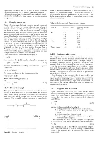
2.1.9 Charging a capacitor Table 2.2 Dielectric strength of some common insuiators
Figure 2.3 shows a parallel plate capacitor which is connected
in series with a resistor to a source of e.m.f. (say, a battery) Material Thickness (rnrn) Dielectric strength
through a switch. Initially. the capacitor is uncharged before (kVlrnm)
the switch is closed. When the switch is closed a charging
current will flow until such time that the potential difference Air 0.2 5.75
across the capacitor is equal to the e.m.f. available from the 0.6 4.92
source. The charging process consists of taking electrons from 1.0 4.36
plate A and transferring them through the external wiring to 10.0 2.98
plate B. The energy -required to do this is derived from the Mica 0.01 200
battery. The build-up of electrons from the negative terminal 0.10 115
of the bi3tteJy to plate B of the capacitor induces a dielectric 1.00 61
flux between the plates and a balancing positive charge is
developed on plate A. As long as the dielectric flux is Waxed paper 0.10 40-60
changing, a current will flow externally. Eventually a state of
equilibrium will be reached. Note that no electrons can pass
through the dielectric since it is an insulator.
The instantaneous current during charging is 2.1.11 Electromagnetic systems
i = dQ/dt The magnetic field can be defined as the space in which a
magnetic effect can be detected, or observed. An obvious
From equation (2.14), this may be written for a capacitor as magnetic field is observable around a straight length of
i = dQ/dt = C(dv/dt) (2.18) conductor carrying a current. In particular, exactly the same
magnetic field as that produced by a bar magnet is observed
where v is the instantaneous voltage. The instantaneous power when the current-carrying conductor is formed into a helical
is thereftore type coil. The equipotential loops describe the path of the
p = iv =: Cv(dv/dt) magnetic flux, 4, and although the flux lines have no physical
meaning, they provide a convenient vehicle to quantify va-
The energy supplied over the time period, dt, is rious magnetic effects.
Cv(dv/dt)dt = Cvdv The direction of the magnetic flux is governed by the
so-called ‘right-hand screw rule’. This states that the direction
Hence the rota! energy supplied is of the magnetic field produced by a current corresponds with
1 the direction given by turning a right-hand screw thread. The
1” Cvdv = - CV2 (2.19) direction of the current corresponds with the translationai
2 movement of the screw.
2.1.10 Dielectric strength 2.1.12 Magnetic field of a toroid
If the potential difference across opposite faces of a dielectric Figure 2.4 shows a toroidal coil, of N turns, which is wound
material is increased above a particular value, the material round an annular former. A resuitant magnetic flux, shown as
breaks down. The failure of the material takes the form of a broken lines in the figure, is generated when the coil carries a
small puncture, which renders the material useless as an current. For the magnetic field, equation (2.1) takes the
insulator. The potential gradient necessary to cause break- general form:
(2.20)
where 4 is the magnetic flux(in webers),
p is the permeability of the medium (in henrysim),
a is the cross-sectional area of the flux path in the
toroid,
-i- 1 is the length of the flux path, and
ft t+
--A F is the magnetic potential difference, or magneto-
motive force (in amperes).
The magnetomotive force (m.rn.f.) is equal to the product
of the number of turns on the coil and the current carried, i.e.
F = IN (2.21)
Note that the m.m.f. is descritively expressed in ‘ampeie-
turns’. Since the number of turns is already a dimensionless
quantity, the accepted unit of magnetomotive force is the
Figure 2.3 Charging a capacitor ampere (A).