
Page 66 - Mechanical Engineers Reference Book
P. 66
Basic electrical technology 2/7
t i A
t
B
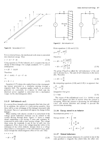
Figure 2.7 Self-induced emf
Figure 2.6 Generation of emf. From equations (2.20) and (2.21)
f$=-=- paF paiN
1 I
For no external losses, the mechanical work done is convertid
into electrical energy. Thus Therefore
e. 1. dt = F. dx (2.26)
Using e’quation (2.25) the induced e.m.f. is equal to the rate of
change of flux linkage. For a single conductor, N = 1, and in
consequence
e = (B . 1. dx)idt
The group N2(pal/) is called the ‘self-inductance’ of the coil
Therefore and is denoted by L. The unit of self-inductance is the henry
(S . I . dxldt) . I. df = F. dx (H). Therefore
di
i.e v = iR + L- (2.30)
F= B. I. I (2.27) dt
By comparing equations (2.28) and (2.30) it is apparent that
Equation (2.27) relates the applied force to the correspond-
ing current generated in a conductor moving through a di dq5
magnetic field. The equation applies equally to an electric L-=N- dt
generator or, conversely, to a motor, in which case the dt
electrical power supplied is converted into a mechanical Integration then gives
torque via the electromagnetic effect.
L = N@i (2.31)
The nature of the self-induced e.m.f. (Le. Ldiidt) is such
that it will oppose the flow of current when the current is
2.1.15 Self-induced e.m.f. increasing. When the current is decreasing the self-induced
e.m.f. will reverse direction and attempt to prevent the
If a current flows through a coil a magnetic flux links that coil.
If, in alddition, the current is a time-varying quantity, then current from decreasing.
there will be a rate of change of flux linkages associated with
the circuit. The e.m.f. generated will oppose the change in flux 2.1.16 Energy stored in an inductor
linkages.
When dealing with electric circuits it is convenient if the Instantaneous power = vi
voltage across individual elements can be related to the
current flowing through them. Figure 2.7 shows a simple Energy stored = W = I’
vidt
circuit comprising a coil having N turns and resistance R,
connected in series with a time-varying voltage. The voltage
drop across the terminals A and B can be split into two
components. First, there is the voltage drop due solely to the
resistance of the coiled element. Second, there is a voltage 1
drop which is a consequence of the self-induced e.m.f. gene- = L 1’ idi = ;LIZ (2.32)
rated through the electromagnetic effect of the coil. Thus
v = vr -t vl 2.1.17 Mutual inductance
d+
= iR + N- (2.28) Two coils possess mutual inductance if a current in one of the
dt coils produces a magnetic flux which links the other coil.