
Page 68 - Mechanical Engineers Reference Book
P. 68
Basic electrical technology 2/9
- r.m.s. = [llf (quantity)’dt 11’* (2.35)
-I* I
! ’1
Many electrical quantities vary in a sinusoidal manner and it
I can easily be shown that the r.m.s. value is simp!y,related to
the maximum value by
I r.m.s. = mad(V2) = 0.707 max (2.36)
I l2 2.1.22 Relationship between voltage and current in R,
L and C elements
For a simple resistive element, current is directly proportional
to voltage. The current waveform will therefore be essentially
the same shape as the voltage waveform.
For an inductive coil with negligible resistance, the relation
between voltage and current is given by equation (2.30), i.e.
di
v = L-
dr
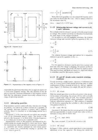
Figure 2.10 Magnetic circuit Thus
i = 1 vdt
L
The relation between voltage and curreni for a capacitive
element is given by equation (2.18), i.e.
For the capacitive element it can be seen that a current will
flow only when the voltage is changing. No current can flow if
the voltage is constant since dvldt will then be equal to zero.
The capacitor then, will block any steady d.c. input and indeed
is sometimes used for this express purpose.
2.1.23 RL and RC circuits under transient switching
conditions
Circuits involving a single resitor, capacitor or inductance are
rare. It is more usual to find circuits involving some or other
Figure 2.11 Representation of the magnetic circuit of Figure 2.10
combination of these elements in both d.c. and a.c. applica-
tions. Figure 2.12 illustrates two simple RL and RC circuits.
reasonably be questioned therefore why air gaps are used at all
in iron-cored magnetic circuits. The only function of the air 2.1.23.1 RL circuit
gap is to provide a measure of linearity to the magnetic system With the switch open there is no flow of current in the circuit.
such that the inductance remains reasonably constant over a At the instant of switching, the current will rise and eventually
range of operating currents. reach a steady-state value of VJR. The transient period is
governed by equation (2.30), which represents a first-order,
ordinary differential equation in i. The solution of equation
2.1.21 Alternating quantities (2.30) involves separating the variables to allow integration.
The general solution is
If an electrical quantity varies with time, but does not change
its polarity, it is said to be a direct current (d.c.) quantity. If i = 1[1 - exp(-RfiL)] (2.38)
the quantity alternates between a positive and a negative Equation (2.38) shows that the current growth in the circuit
polarity, then it is classified as an alternating current (a.c.)
quantity. will rise exponentially to reach a steady state value as time, t,
The period. T, is the time interval over which one complete increases. It may also be shown that
cycle of the alternating quantity varies. The inverse of the di
period is the frequency, f, in Hertz (Hz). Circular frequency, v = L - = V, . exp(-RdL) (2.39)
dt
w, in radians per second is also commonly used.
Instantaneous values of the quantities encountered in elec- The ‘time constant’, T, for the RL circuit is LIR.
trical systems are usually denoted by lower-case letters. Since
the instantaneous values are difficult to measure and quantify, 2.1.23.2 RC circuit
a.c. quantities are usuaily expressed as ‘root mean square‘
(r.m.s.:i values. For a periodically varying a.c. quantity, the In Figure 2.12(b), with the switch open there is zero potential
r.m.s. value is given by difference across the capacitor. On closing the switch the