
Page 65 - Mechanical Engineers Reference Book
P. 65
2/6 Electrical and electronics principles
e = N(di#J/dt) (2.25)
where e is the instantaneous induced e.m.f.
Equation (2.25) forms the basis of all electrical power
generation machines and is a statement of the fact that an
electric current can be produced by the movement of magnetic
flux relative to a coil. In all rotating electrical generators it is
actually the coil which is moved relative to the magnetic field.
The net result, however, is exactly the same.
The direction of the induced emf. is always such that it
tends to set up a current to oppose the motion (or the change
of magnetic flux) which was responsible for inducing the
e.m.f. This is essentially a statement of Lenz’s law. In many
texts, therefore, the right-hand side of equation (2.25) is often
Area a shown as a negative quantity.
The motion, or change of flux, is associated with the
application of a mechanical force which ultimately provides
the torque required to drive the electric generator. Figure 2.6
shows a single conductor of length 1 metres, carrying an
induced current I and lying perpendicular to a magnetic field
Figure 2.4 Toroid of flux density, B T.
The force applied causes the conductor to move through a
The group (pull) is termed the permeance and the inverse of distance dx metres. The mechanical work done is therefore
permeance is the reluctance, S. Thus equation (2.20) may be F. dx. The electrical energy produced is given as the product
rewritten as of the power developed and the time duration, i.e. e . I. dt.
i#J = FIS (2.22)
Equation (2.22) represents an electromagnetic version of
Ohm’s law.
Alternatively, equation (2.20) can be expressed as
_- i#JF
- PT
or
B = pH (2.23)
where B = i#J/u is the magnetic flux density (in webers/m2, or
Tesla (T)) and H = F/l is the magnetic intensity (in Nm).
2.1.13 Permeability
The permeability of free space, PO, is numerically equal to
4a x lo-’. The absolute permeability of other materials is
related to the permeability of free space by the relative
permeability, i.e.
P = Po ‘ PLr (2.24)
For air and other non-magnetic materials, the absolute
permeability is the same constant. For magnetic materials,
absolute permeability is not a fixed constant but varies non-
linearly with the flux density. The non-linear variation of
permeability is conveniently displayed as a functional plot of
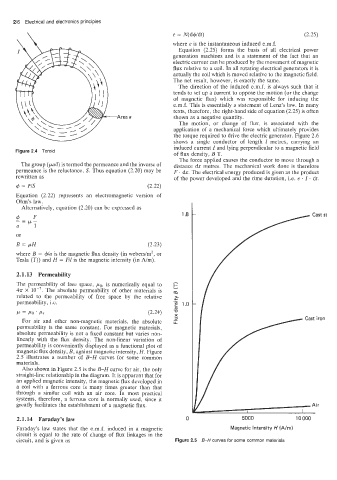
magnetic flux density, B, against magnetic intensity, H. Figure
2.5 illustrates a number of B-H curves for some common
materials.
Also shown in Figure 2.5 is the B-H curve for air, the only
straight-line relationship in the diagram. It is apparent that for
an applied magnetic intensity, the magnetic flux developed in
a coil with a ferrous core is many times greater than that
through a similar coil with an air core. In most practical
systems, therefore, a ferrous core is normally used, since it
greatly facilitates the establishment of a magnetic flux.
2.1.14 Faraday’s law 5000 10 000
Faraday’s law states that the e.m.f. induced in a magnetic Magnetic intensity H (A/rn)
circuit is equal to the rate of change of flux linkages in the
circuit, and is given as Figure 2.5 6-H curves for some common materials