
Page 69 - Mechanical Engineers Reference Book
P. 69
2/10 Electrical and electronics principles
i i
i
(a)
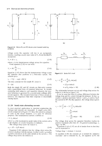
Figure 2.12 Simple RL and RC circuits under transient switching
conditions
voltage across the capacitor will rise in an asympototic
manner, reaching a steady-state value of V,. From Kirchhoff‘s
second law:
V, = iR + v, (2.40)
where v, is the instantaneous voltage across the capacitor.
From equation (2.18) we can write:
dv
V, = RCC + vc (2.41)
dt
Equation (2.41) shows that the instantaneous voltage across Figure 2.13 Series RLC circuit
the capacitor also conforms to a first-order system. The
solution gives
di
d
v, = Vs[l - exp(-t/RC)] (2.42) vL = L - = L - [I,,, sin(ot)]
The time constant for the simple RC circuit is dt dt
T= RC (2.43) = LZ,W cos(wt)
Both the simple RL and RC circuits are first-order systems = wLI, sin(wt + 90) (2.46)
with a generalized form of transient behaviour. In circuits
containing both inductive and capacitive elements the tran- The relationship between current and voltage drop across the
sient behaviour is governed by a second-order ordinary diffe- inductor is shown in Figure 2.14.
rential equation. The transient behaviour of these circuits is, It can be seen that there is a phase difference between the
however, less important than their response to sinusoidally voltage drop and the current through the inductor. In fact, vL
varying inputs. reaches a positive maximum ‘before’ i and vL is said to ‘lead’
the current by 90”. For the capacitor, the voltage drop is given
by
2.1.24 Steady-state alternating currents v, = 1/C 1 idt = l/C I sin(wt)dt
I,,,
In most practical applications in electrical engineering the
voltages and currents are sinusoidal. A simple series RLC Iln
-
circuit is depicted in Figure 2.13. Since the current is common - -- COS(Wt)
WC
to each of the circuit elements, it is used for reference
purposes. The instantaneous current is defined as
= + - sin(wt - 90) (2.47)
i = I, sin(ot) (2.44) WC
where I, is the maximum (or peak) value of the current and w The voltage drop across the capacitor therefore reaches its
is the angular. or circular frequency in radiansis. positive maximum after that of i. In general terminology, v,
The voltage drop across the resistor is ‘lags’ i by 90”.
Equations (2.45)-(2.47) are all of similar form in that they
VR = iR = I,R sin(ot) (2.45) can be expressed as
Equation (2.45) indicates that the voltage drop across the Voltage drop = constant X current
resistor is in phase with the current. In other words, vR reaches
a positive maximum at the same instant as the current, i. The In equation (2.46) the constant WL is termed the ‘inductive
voltage drop across the inductor is reactance’ and is denoted by X,. In equation (2.47) the