
Page 70 - Mechanical Engineers Reference Book
P. 70
Basic electrical technology 2/11
"R
Figure 2.15 Phasor diagram for series RLC circuit
2.1.26 Complex notation
Since inductive and capacitive elements in a.c. circuits involve
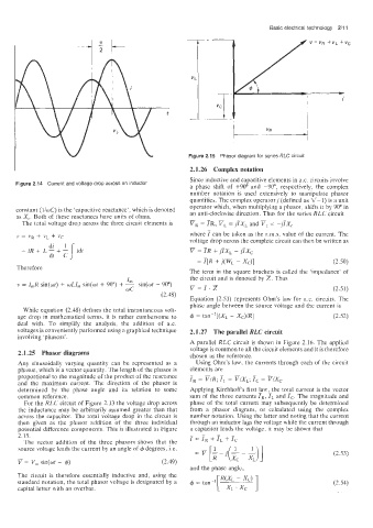
Figure 2.14 Current and voltage drop across an inductor a phase shift of +90° and -90", respectively. the complex
number notation is used extensively to manipulate phasor
quantities. The complex operator j (defined as v-1) is a unit
operator which, when multiplying a phasor, shifts it by 90" in
constant (lid) is the 'capacitive reactance', which is denoted an anti-clockwise direction. Thus for the series RLC circuit
as X,. Both of these reactances have units of ohms. -
The total voltage drop across the three circuit elements is VR = TR, v, = jiXL and 7, = -jiXc
v = VR + VL + vc where 7 can be taken as the r.m.s. value of the current. The
voltage drop across the complete circuit cap, then be written as
-
= iR + L 5 + L 1 idt v = IR + jixL - jix,
dt C
= T[R + j(WL - X,)] (2.50)
Therefore
The term in the square brackets is called the 'imqxdance' of
the circuit and is denoted by Z. Thus
-
~~7.z (2.51)
Equation (2.51) represents Ohm's law for ax. circuits. The
phase angle between the source voltage and the current is
While equation (2.48) defines the total instantaneous volt-
age drop in mathematical terms, it is rather cumbersome to 4 = tan-'[(X, - x~)/R] (2.52)
deal with. To simplify the analysis, the addition of a.c.
voltages is conveniently performed using a graphical technique 2.1.27 The parallel RLC circuit
involving 'phasors'.
A parallel RLC circuit is shown in Figure 2.16. The applied
voltage is common to all the circuit elements and it is therefore
2.1.25 Phasor diagrams chosen as the reference.
Any sinusoidally varying quantity can be represented as a Using Ohm's law, the currents through each of the circuit
phasor, which is a vector quantity. The length of the phasor is elements are
proportional to the magnitude of the product of the reactance
and the maximum current. The direction of the phasor is
determined by the phase angle and its relation to some Applying Kirchhoff's first iaw,-the tot_al current is the vector
common reference. sum of the three currents IR, 1, and IC. The magnitude and
For the RLC circuit of Figure 2.13 the voltage drop across phase of the total current may subsequently be determined
the inductance may be arbitrarily assumed greater than that from a phasor diagram, or calculated using the complex
across the capacitor. The total voltage drop in the circuit is number notation. Using the latter and noting that the current
then given as the phasor addition of the three individual through an inductor lags the voltage while the current through
potential difference components. This is illustrated in Figure a capacitor leads the voltage, it may be shown that
+
2.15. i = 7, + iL ic
The vector addition of the three phasors shows that the
source voltage leads the current by an angle of 4 degrees, i.e. (2.53)
-
V = V, sin(& + 4) (2.49)
and the phase angle,
The circuit is therefore essentially inductive and, using the
standard notation, the total phasor voltage is designated by a (2.54)
capita! letter with an overbar.