
Page 75 - Mechanical Engineers Reference Book
P. 75
2/16 Electrical and electronics principles
Coil voltage output
(b)
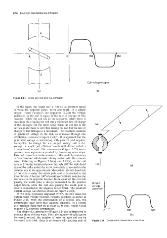
Figure 2.24 Single-coil, two-pole d.c. generator
In the figure the single coil is rotated at constant speed
between the opposite poles, north and south, of a simple
magnet. From Faraday's law (equation (2.25)) the voltage
generated in the coil is equal to the rate of change of flux
linkages. When the coil lies in the horizontal plane there is
maximum flux linking the coil but a minimum rate of change
of flux linkages. On the other hand, when the coil lies in the
vertical plane there is zero flux linking the coil but the rate of
change of flux linkages is a maximum. The resultant variation
in generated voltage in the coil, as it moves through one
revolution, is shown in Figure 2.24(b). It is apparent that the
generated voltage is alternating with positive and negative
half-cycles. To change the a.c. output voltage into a d.c.
voltage, a simple yet effective mechanical device called a
'commutator' is used. The commutator (Figure 2.25) incor-
porates brass segments separated by insultating mica strips.
External connection to the armature coil is made by stationary -ve T
carbon 'brushes' which make sliding contact with the commu-
tator. Referring to Figures 2.24(a) and 2.25(a), as the coil
rotates from the horizontal plane through 180" the right-hand
side of the coil is under the north pole and is connected via the
commutator to the upper brush. Meanwhile, the left-hand side
of the coil is under the south pole and is connected to the
lower brush. A further 180" of rotation effectively switches the
coil sides to the opposite brushes. In this manner the coil side
passing the north pole is always connected to the positive output
upper brush, while the coil side passing the south pole is voltage
always connected to the negative lower brush. The resultant wavefo r rn
output voltage waveform is shown in Figure 2.25(b).
If two coils, physically displaced by 90°, are now used, the
output brush voltage becomes virtually constant, as shown in
Figure 2.26. With the introduction of a second coil, the
commutator must have four separate segments. In a typical
d.c. machine there may be as many as 36 coils, which would
require a 72-segment commutator.
The simple d.c. generator of Figure 2.24 can be improved in 0 180 360
perhaps three obvious ways. First, the number of coils can be (b)
increased, second, the number of turns on each coil can be
increased and third, there is no reason why another pair of Figure 2.25 Commutator connections to armature