
Page 80 - Mechanical Engineers Reference Book
P. 80
Electrical machines 2/21
I Rated
I speed
Applied voltage, V
Armature current Speed
(a) (b)
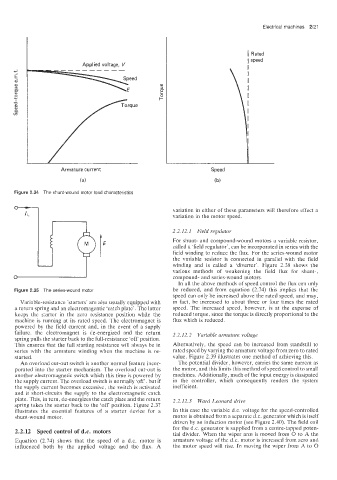
Figure 2!.34 The shunt-wound motor load characteristics
variation in either of these parameters will therefore effect a
IL variation in the motor speed.
2.2.12.1 Field regulator
E For shunt- and compound-wound motors a variable resistor,
called a ‘field regulator‘, can be incorporated in series with the
field winding to reduce the flux. For the series-wound motor
the variable resistor is connected in parallel with the field
winding and is called a ‘diverter’. Figure 2.38 shows the
various methods of weakening the field flux for shunt-,
compound- and series-wound motors.
In all the above methods of speed control the flux can only
Figure :!.35 The series-wound motor be reduced, and from equation (2.74) this implies that the
speed can only be increased above the rated speed, and may,
Variable-resistance ’starters’ are also usually equipped with in fact, be increased to about three or four times the rated
a return spring and an electromagentic ‘catch plate’. The latter speed. The increased speed, however, is at the expense of
keeps the starter in the zero resistance position while the reduced torque, since the torque is directly proportional to the
machine is running at its rated speed. The electromagnet is flux which is reduced.
powered by the field current and, in the event of a supply
failure. the electromagnet is de-energized and the return 2.2.12.2 Variable armature voltage
spring pulls the starter back to the full-resistance ‘off‘ position.
This ensures that the full starting resistance will always be in Alternatively. the speed can be increased from standstill to
series .with the armature winding when the machine is re- rated speed by varying the armature voltage from zero to rated
started. value. Figure 2.39 illustrates one method of achieving this.
An overload cut-out switch is another normal feature incor- The potential divider, however, carries the same current as
porated into the starter mechanism. The overload cut-out is the motor, and this limits this method of speed control to small
another electromagnetic switch which this time is powered by machines. Additionally, much of the input energy is dissipated
the supply current. The overload switch is normally ‘off‘. but if in the controller, which consequently renders the system
the supply current becomes excessive, the switch is activated inefficient.
and it short.-circuits the supply to the electromagnetic catch
plate. This, in turn. de-energizes the catch plate and the return 2.2.12.3 Ward Leonard drive
spring takes the starter back to the ‘off‘ position. Figure 2.37
illustrates the essential features of a starter device for a In this case the variable d.c. voltage for the speed-controlled
shunt-wound motor. motor is obtained from a separate d.c. generator which is itself
driven by an induction motor (see Figure 2.40). The field coil
for the d.c. generator is supplied from a centre-tapped poten-
2.2.12 Speed conUrol of d.c. motors tial divider. When the wiper arm is moved from 0 to A the
Equatimon (2’74) shows that the speed of a d.c. motor is armature voltage of the d.c. motor is increased from ZCKJ and
influenced both by the applied voltage and the flux. A the motor speed will rise. In moving the wiper from A to 0