
Page 81 - Mechanical Engineers Reference Book
P. 81
2/22 Electrical and electronics principles
+ Applied voltage, V
Armature current Speed
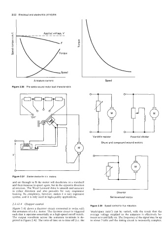
Figure 2.36 The series-wound motor load characteristics
Variable resistor Potential divider
4)
f
0 /
/
2.2.12.4 Chopper control
-
Fiaure 2.38 Sueed control for flux reduction
Figure 2.41 shows a thyristor circuit connected in series with
the armature of a d.c. motor. The thyristor circuit is triggered ‘markkpace ratio’) can be varied, with the result that the
such that it operates essentially as a high-speed onioff switch. average voltage supplied to the armature is effectively be-
The output waveform across the armature terminals is de- tween zero and fully on. The frequency of the signal may be up
picted in Figure 2.42. The ratio of time on to time off (Le. the to about 3 kHz and the timing circuit is necessarily complex.