
Page 85 - Mechanical Engineers Reference Book
P. 85
2/26 Electrical and electronics principles
Section 2.2.21). A second method uses a wound rotor similar coils and subsequently no electromagnetic torque. Induction
to a slip-ring induction motor. The machine is run up to speed motors therefore always run at something less than synchro-
as an induction motor and is then pulled into synchronism to nous speed. The ratio of the difference between the synchro-
operate as a synchronous motor. nous speed and the rotor speed to the synchronous speed is
The advantages of the synchronous motor are the ease with called the ‘slip’, s, i.e.
which the power factor can be controlled and the constant N, - N
rotational speed of the machine, irrespective of the applied s=- (2.82)
load. Synchronous motors, however, are generally more ex- N,
pensive and a d.c. supply is a necessary feature of the rotor The torque-slip characteristic is shown in Figure 2.50. With
excitation. These disadvantages, coupled with the require- the rotor speed equal to the synchronous speed, i.e. s = 0, the
ment for an independent starting mode, make synchronous torque is zero. As the rotor falls below the synchronous speed
motors much less common than induction ones.
the torque increases almost linearly to a maximum value
dictated by the total of the load torque and that required to
2.2.21 Induction motors overcome the rotor losses. The value of slip at full load varies
between 0.02 and 0.06. The induction motor may be regarded
The stator of an induction motor is much like that of an therefore as a constant-speed machine. In fact the difficulties
alternator and, in the case of a machine supplied with three- of varying the speed constitutes one of the induction motor’s
phase currents, a rotating magnetic flux is produced. The rotor main disadvantages.
may be either of two basic configurations: the ‘squirrel-cage’ On start-up, the slip is equal to unity and the starting torque
or the slip-ring type. In the squirrel-cage motor the rotor core is sufficiently large to accelerate the rotor. As the rotor runs
is laminated and the conductors consist of uninsulated copper up to its full-load speed the torque increases in essentially
(or aluminium) bars driven through the rotor slots. The bars inverse proportion to the slip. The start-up and running curves
are brazed or welded at each end to rings or plates to produce merge at the full-load position.
a completely short-circuited set of conductors. The slip-ring
machine has a laminated core and a conventional three-phase 2.2.22 Starting induction motors
winding, similar to the stator and connected to three slip-rings
on the locating shaft. As with d.c. motors, the current drawn during starting of a.c.
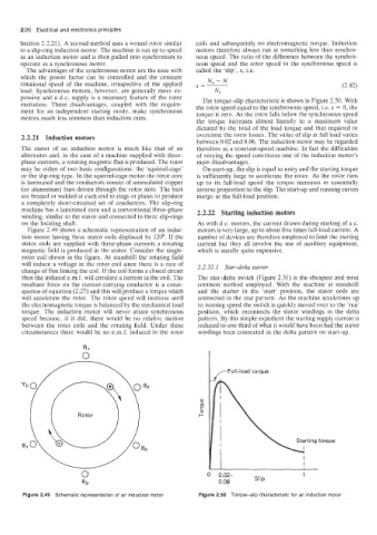
Figure 2.49 shows a schematic representation of an induc- motors is very large, up to about five times full-load current. A
tion motor having three stator coils displaced by 120”. If the number of devices are therefore employed to limit the starting
stator coils are supplied with three-phase currents a rotating current but they all involve the use of auxiliary equipment,
magnetic field is produced in the stator. Consider the single- which is usually quite expensive.
rotor coil shown in the figure. At standstill the rotating field
will induce a voltage in the rotor coil since there is a rate of 2.2.22.1 Star-delta starter
change of flux linking the coil. If the coil forms a closed circuit
then the induced e.m.f. will circulate a current in the coil. The The star-delta switch (Figure 2.51) is the cheapest and most
resultant force on the current-carrying conductor is a conse- common method employed. With the machine at standstill
quence of equation (2.27) and this will produce a torque which and the starter in the ‘start’ position, the stator coils are
will accelerate the rotor. The rotor speed will increase until connected in the star pattern. As the machine accelerates up
the electromagnetic torque is balanced by the mechanical load to running speed the switch is quickly moved over to the ’run’
torque. The induction motor will never attain synchronous position, which reconnects the stator windings in the delta
speed because, if it did, there would be no relative motion pattern. By this simple expedient the starting supply current is
between the rotor coils and the rotating field. Under these reduced to one third of what it would have been had the stator
circumstances there would be no e.m.f. induced in the rotor windings been connected in the delta pattern on start-up.
,-Full-load torque
Starting torque
\ v
I1 I I
0 0.02- slip 1
0.06
Figure 2.49 Schematic representation of an induction motor Figure 2.50 Torqueslip characteristic for an induction motor