
Page 82 - Mechanical Engineers Reference Book
P. 82
Electrical machines 2/23
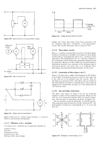
Time
Figure 2.42 Voltage across armature terminals
Figure 2.39 Speed control by varying armature voltage
Despite the variety and nature of the losses associated with
d.c. machines, they have, nonetheless, a very good perfor-
mance with overall efficiencies often in excess of 90%.
2.2.14 Three-phase circuits
Since a.c. machines are generally associated with three-phase
systems it is necessary to consider some aspects of three-phase
circuits before a meaningful discussion of a.c. machines can be
undertaken. The limiting factor of a d.c. machine is related to
the commutator which restricts the maximum voltage that can
be generated. Because of their efficiency and performance,
three-phase machines have emerged as the dominant type of
electrical generator and motor and, on a worldwide basis,
three-phase electrical distribution networks are the norm.
2.2.15 Generation of three-phase e.m.f.'s
Figure 2.43 shows three similar coils displaced at 120" relative
Figure 2.40 Ward Leonard drive
to each other. Each loop terminates in a pair of .slip-rings' and
if the coils are to be isolated from one another, then six
slip-rings are required in total. If the three coils are rotated in
the anti-clockwise direction at constant speed, then each coil
will generate a sinusoidally varying e.m.f. with a phase shift of
120" between them.
2.2.16 Star and delta connections
The three coils shown in Figzre 2.43 can be connected
together in either of two symmetrical patterns. These are the
'star' (or 'wye') connection and the 'delta' (or 'mesh') connec-
tion. The two types of connection are shown in Figure 2.44.
The star pattern is made by joining Ro. YO and Bo together.
This connection point is referred to as the 'neutral point'. The
delta pattern is formed by connecting Ro to Y1, Yo to B1 and
Bo to R1.
Figure 2.41 Speed control using thyristors
Speed control of d.c. motors using thyristors, is, however,
effective and relatively inexpensive.
2.2.13 Efficiency of d.c. machines
The losses in d.c. machines can be generally classified as:
Armature losses,
Iron loss,
Commutator losses,
Excitation loss. and
Bearing friction and windage Figure 2.43 Generation of three-phase e.rn.f.'s