
Page 84 - Mechanical Engineers Reference Book
P. 84
Electrical machines 2/25
where N, is the speed of the field (revimin) and f is the
frequency of the supply currents. The speed of the rotating
field is termed the ‘synchronous speed’ and for an equivalent
single pair of poles (i.e. three coils) this is 3000 revimin when
the frequency of the supply curients is at 50 Hz.
The use of a.c. excited rotor coiis to produce the rotating
magnetic field simplifies the mechanical construction of the
rotor and greatly facilitates the dynamic balancing of the
machine. An added advantage is that the waveform of the
generated voltage is improved. The a.c. method of exciting the
field is used extensively in large alternators. Salient pole rotors
are normally restricted to the smaller machines.
2.2.20 Synchronous motors
Synchronous motors are so called because they operate at only
one speed, i.e. the speed of the rotating field. The mechanical
construction is exactly the same as the alternator shown in
Figure 2.47. The field is supplied from a d.c. source and the
stator coils with a three-phase current. The rotating magnetic
field is induced by the stator coils and the rotor, which may be
I I likened to a permanent bar magnet, aligns itself to the rotating
flux produced in the stator. When a mechanical load is driven
by the shaft the field produced by the rotor is pulled out of
alignment with that produced by the stator. The angle of
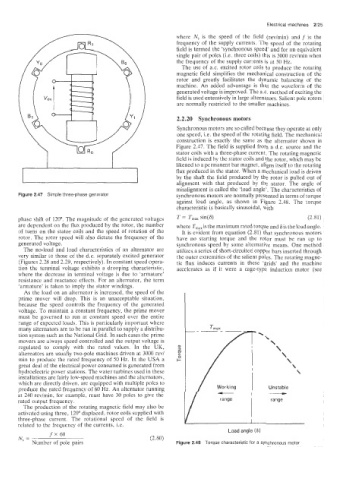
misalignment is called the ‘load angle’. The characteristics of
Figure 2.47 Simple three-phase generator synchronous motors are normally presented in terms of torque
against load angle, as shown in Figure 2.48. The torque
characteristic is basically sinusoidal, with
phase shift of 120”. The magnitude of the generated voltages T = T,,, sin(8) (2.81)
are dependent on the flux produced by the rotor, the number where T,,, is the maximum rated torque and 6 is the load angle.
3f turn(; on the stator coils and the speed of rotation of the It is evident from equation (2.81) that synchronous motors
rotor. The rotor speed will also dictate the frequency of the have no starting torque and the rotor must be run :up tQ
generated voltage. synchronous speed by some alternative means. One method
The no-load and load characteristics of an alternator are utilizes a series of short-circuited copper bars inserted through
very similar io those of the d.c. separately excited generator the outer extremities of the salient poles. The rotating magne-
(Figures 2.28 and 2.29, respectively). In constant speed opera- tic flux induces currents in these ‘grids’ and the machine
tion the terminal voltage exhibits a drooping characteristic, accelerates as if it were a cage-type induction motor (see
where the decrease in terminal voltage is due to ’armature’
resistance and reactance effects. For an alternator, the term
‘armature’ is taken to imply the stator windings.
As the load on an alternator is increased, the speed of the
pime mover will drop. This is an unacceptable situation,
because the speed controls the frequency of the generated
voltage. To maintain a constant frequency, the prime mover
must be governed to run at constant speed over the entire
range of expected loads. This is particularly important where
many alternators are to be run in parallel to supply a distribu-
tion system such as the National Grid. In such cases the prime
movers are aiways speed controlled and the output voltage is
regulated to comply with the rated values. In the UK, er
3
akernators are usually two-pole machines driven at 3000 rev/ IT
min to produce the rated frequency of 50 Hz. In the USA a c
great deal of the electrical power consumed is generated from
hydroelectric power stations. The water turbines used in these
installations are fairly low-speed machines and the alternators,
which aire directly driven, are equipped with multiple poles to
produce the rated frequency of 60 Hz. An alternator running Unstable
at 240 revimin, for example, must have 30 poles to give the
rated output frequency.
The production of the rotating magnetic field may also be
activated using three, 120” displaced, rotor coils supplied with
three-phase current. The rotational speed of the field is I
related ‘to the frequency of the currents, Le.
Load angle (6)
fx60
N =- (2.80)
Number of pole pairs Figure 2.48 Torque characteristic for a synchronous motor