
Page 98 - Mechanical Engineers Reference Book
P. 98
Analogue and digital electronics theory 2/39
t”
I
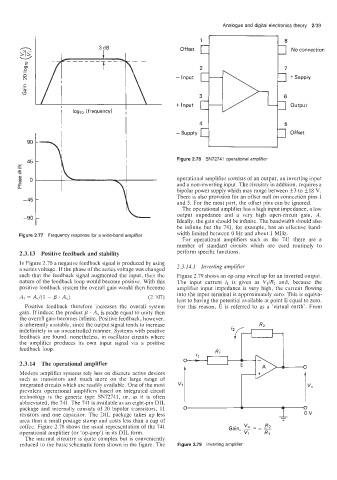
Offset No connection
0 - Input *Supply
(v
.-
C
d
i loglo (frequency) , I + Input Output
I I Offset
Figure 2.78 SN72741 operational amplifier
operational amplifier consists of an output, an inverting input
and a non-inverting input. The circuitry in addition, requires a
bipolar power supply which may range between +3 to f18 V.
There is also provision for an offset null on connection pins 1
and 5. For the most part, the offset pins can be ignored.
The operational amplifier has a high input impedance, a low
output impedance and a very high open-circuit gain, A.
Ideally, the gain should be infinite. The bandwidth should also
be infinite but the 741, for example, has an effective band-
Figure 2.77 Frequency response for a wide-band amplifier width limited between 0 Hz and about 1 MHz.
For operational amplifiers such as the 741 there are a
number of standard circuits which are used routinely to
2.3.13 Positive feedback and stability perform specific functions.
In Figure 2.76 a negative feedback signal is produced by using
a series voltage. If the phase of the series voltage was changed 2.3.14.1 Inverting amplifier
such thal. the feedback signal augmented the input, then the Figure 2.79 shows an op-amp wired up for an inverted output.
nature of the feedback loop would become positive. With this The input current il is given as Vl/Rl and, because the
positive feedback system the overall gain would then become amplifier input impedance is very high, the current flowing
into the input terminal is approximately zero. This is equiva-
AI = AJ(1 - p . A,) (2.107)
lent to having the potential available at point E equal to zero.
Positive feedback therefore increases the overall system For this reason, E is referred to as a ’virtual earth’. From
gain. If indeed the product p . A, is made equal to unity then
the overail gain becomes infinite. Positive feedback, however,
is inherently unstable, since the output signal tends to increase
indefinitely in an uncontrolled manner. Systems with positive
feedback are found, nonetheless, in oscillator circuits where
the ampiifier produces its own input signal via a positive
feedback loop.
2.3.14 The operational amplifier
Modern amplifier systems rely less on discrete active devices
such as transistors and much more on the large range of
integrated circuits which are readily available. One of the most
prevalent operational amplifiers based on integrated circuit
technology is the generic type SN72741, or, as it is often
abbreviated, the 741. The 741 is available as an eight-pin DIL
package and internally consists of 20 bipolar transistors, 11
resistors and one capacitor. The DIL package takes up less
area than a small postage stamp and costs less than a cup of
coffee. Figure 2.78 shows the usual representation of the 741
operational amplifier (or ‘op-amp’) in its DIL form.
The internal circuitry is quite complex but is conveniently
reduced to the basic schematic form shown in the figure. The Figure 2.79 Inverting amplifier