
Page 14 - Mechanical Engineers Reference Book
P. 14
Strength of materials 113
In general, the study of mechanics may be divided into two i = ZSmg . zlZ6mg
distinct areas. These are statics, which involves the study of
bodies at rest, and dynamics, which is the study of bodies in where Sm is an element of mass at a distance of x, y or z from
the respective axis, and X, j and i are the positions of the
motion. In each case it is important to select an appropriate centres of gravity from these axes. Table 1.1 shows the
mathematical model from which a ‘free body diagram’ may be position of the centre of gravity for some standard shapes.
drawn, representing the system in space, with all the relevant (See reference 2 for a more comprehensive list.)
forces acting on that system.
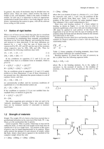
Shear force and bending moment: If a beam subject to
loading, as shown in Figure 1.1, is cut, then in order to
maintain equilibrium a shear force (Q) and a bending moment
Statics of rigid bodies (M) must be applied to each portion of the beam. The
magnitudes of Q and M vary with the type of loading and the
position along the beam and are directly related to the stresses
When a set of forces act on a body they give rise to a resultant
force or moment or a combination of both. The situation may and deflections in the beam.
be determined by considering three mutually perpendicular Relationship between shear force and bending moment: If an
directions on the ‘free body diagram’ and resolving the forces element of a beam is subjected to a load w then the following
and moment in these directions. If the three directions are relationship holds:
denoted by n? y and z then the sum of forces may be d2M dF
represented by ZFx, .ZFy and ZF, and the sum of the moments --
-W
about respective axes by 2M,, SM, and 2Mz. Then for dx2 dx
equilibrium the following conditions must hold:
Table 1.2 shows examples of bending moments. shear force
2Fx =2Fy =2Fz =O (1.1) and maximum deflection for standard beams.
ZMx = 2My = ZMz = 0 (1.2) Bending equation: If a beam has two axes of symmetry in
If th’e conditions in equations (1.1) and (1.2) are not the xy plane then the following equation holds:
satisfied then there is a resultant force or moment, which is MZIIz = EIRZ = dy
given by
where Mz is the bending moment, RZ is the radius of
curvature, Zz the moment of inertia, E the modulus of
elasticity, y the distance from the principal axis and u is the
The six conditions given in equations (1.1) and (1.2) satisfy stress.
problems in three dimensions. If one of these dimensions is
not present (say: the z direction) the system reduces to a set of
cop1ana.r forces, and then
ZF, = .CM, = 2My = 0
are automatically satisfied, and the necessary conditions of
equiiibrium in a two-dimensional system are
2Fx = .CFy = ZMz = 0 (1.3) @A
If the conditions in equation (1.3) are not satisfied then the
resultant force or moment is given by
The above equations give solutions to what are said to be
‘statically determinate’ systems. These are systems where
there are the minimum number of constraints to maintain
equilibrium.’
t RA
1.2 Strength of materials
Weight: The weight (W) of a body is that force exerted due to
gravitational attraction on the mass (m) of the body: W = mg,
where g is the acceleration due to gravity. I lQ
Centre of gravity: This is a point, which may or may not be
within the body, at which the total weight of the body may be
considered to act as a single force. The position of the centre
of gravity may be found experimentally or by analysis. When
using analysis the moment of each element of weight, within
the body, about a fixed axis is equated to the moment of the
complete weight about that axis:
x = PSmg. xlZdmg, = SSmg 1 ylZSmg, Figure 1.1