
Page 19 - Mechanical Engineers Reference Book
P. 19
1/8 Mechanical engineering principles
't P 1.3.6 Balancing of rotating masses
1.3.6.1 Single out-of-balance mass
One mass (m) at a distance r from the centre of rotation and
rotating at a constant angular velocity w produces a force
mw2r. This can be balanced by a mass M placed diametrically
opposite at a distance R, such that MR = mr.
t
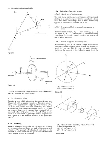
v 1.3.6.2 Several out-of-balance masses in one transverse
plane
If a number of masses (ml, m2, . . . ) are at radii (II, r2, . . . )
and angles (el, e,, . . . ) (see Figure 1.9) then the balancing
Y mass M must be placed at a radius R such that MR is the vector
sum of all the mr terms.
1.3.6.3 Masses in different transverse planes
If the balancing mass in the case of a single out-of-balance
mass were placed in a different plane then the centrifugal force
would be balanced. This is known as static balancing.
However, the moment of the balancing mass about the
Figure 1.7
't
V
Precession axis
5%
Spin axis
axis
X
Figure 1.8
CFx = Crnw2r sin 0 = 0
CFy = Crnw2r cos 0 = 0
In all the vector notation a right-handed set of coordinate axes Figure 1.9
and the right-hand screw rule is used.
1.3.4.2 Gyroscopic efjects
Consider a rotor which spins about its geometric axis (see
Figure 1.8) with an angular velocity w. Then two forces F
acting on the axle to form a torque T, whose vector is along
the x axis, will produce a rotation about the y axis. This is
known as precession, and it has an angular velocity 0. It is also
the case that if the rotor is precessed then a torque Twill be
produced, where T is given by T = IXxwf2. When this is
observed it is the effect of gyroscopic reaction torque that is
seen, which is in the opposite direction to the gyroscopic
torq~e.~
1.3.5 Balancing
CFx = Zrnw2r sin 0 = 0 and ZFy = Zrnw2r cos 0 = 0
In any rotational or reciprocating machine where accelerations as in the previous case, also
are present, unbalanced forces can lead to high stresses and ZM~ Zrnw2r sin e . a = o
=
vibrations. The principle of balancing is such that by the zMy = Crnw2r cos e .a = 0
addition of extra masses to the system the out-of-balance
forces may be reduced or eliminated. Figure 1.10