
Page 21 - Mechanical Engineers Reference Book
P. 21
1/10 Mechanical engineering principles
Table 1.3
End conditions Trig. equation PI1 Solutions P31
- COS pl . cash 01 = 1 1.875 4.694 7.855
P21
x = 0, y = 0, y‘ = 0
4.730
7.853
10.966
+
x = 1, y = 0, y‘ = 0
x = 0, y = 0, y‘ = 0
COS pl . cash pl = -1
x = 1, y“ = 0, y”’ = 0
9.425
x = 0, y = 0, y” = 0
x=l,y=O,y”=O
tan Pl = tanh Pl
7.069
x = 0, y = 0, y’ = 0 sin Pl = 0 3.142 6.283 10.210
3.927
5 x=l,y=O,y”=O
Then the natural frequency of vibration of the complete
system U, is given by
1
1
_-_ 1 1 1 1
- +-+-+-+....-
f2 f; f? f: fS fi
(see reference 7 for a more detailed explanation).
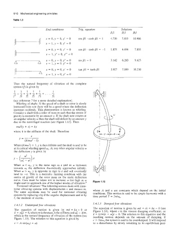
Whirling of shafts: If the speed of a shaft or rotor is slowly
increased from rest there will be a speed where the deflection
increases suddenly. This phenomenon is known as whirling.
Consider a shaft with a rotor of mass m such that the centre of
gravity is eccentric by an amount e. If the shaft now rotates at
an angular velocity w then the shaft will deflect by an amount y
due to the centrifugal reaction (see Figure 1.12). Then
mw2(y + e) = ky
where k is the stiffness of the shaft. Therefore
e
= (k/mw* -1)
When (k/mw2) = 1, y is then infinite and the shaft is said to be
at its critical whirling speed wc. At any other angular velocity w
the deflection y is given by
When w < w,, y is the same sign as e and as w increases
towards wc the deflection theoretically approaches infinity.
When w > w,, y is opposite in sign to e and will eventually
tend to -e. This is a desirable running condition with the
centre of gravity of the rotor mass on the static deflection
curve. Care must be taken not to increase w too high as w Figure 1.12
might start to approach one of the higher modes of vibration.8
Torsional vibrations: The following section deals with trans-
verse vibrating systems with displacements x and masses m. where A and a are constants which depend on the initial
The same equations may be used for torsional vibrating conditions. This motion is said to be simple harmonic with a
systems by replacing x by 8 the angular displacement and m by time period T = 2?r/w,.
I, the moment of inertia.
1.4.1.3 Damped free vibrations
1.4.1.2 Undamped free vibrations
The equation of motion is given by mi! + d + kx = 0 (see
The equation of motion is given by mi! + kx = 0 or Figure 1.14), where c is the viscous damping coefficient, or
x + wix = 0, where m is the mass, k the stiffness and w: = k/m,
which is the natural frequency of vibration of the system (see x + (c/m).i + OJ;X = 0. The solution to this equation and the
resulting motion depends on the amount of damping. If
Figure 1.13). The solution to this equation is given by
c > 2mw, the system is said to be overdamped. It will respond
x = A sin(w,t + a) to a disturbance by slowly returning to its equilibrium posi-