
Page 25 - Mechanical Engineers Reference Book
P. 25
1/14 Mechanical engineering principles
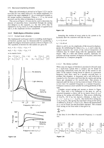
When this information is plotted as in Figure 1.22 it can be
seen that for very small values of w the output amplitude Xis
equal to the input amplitude Y. As w is increased towards w,
the output reaches a maximum. When w = g2 w, the curves
intersect and the effect of damping is reversed.
The curves in Figure 1.22 may also be used to determine the
amount of sinusoidal force transmitted through the springs d
and dampers to the supports, Le. the axis (X/Y) may be //// // / / /// ///////A
replaced by (F,IFo) where Fo is the amplitude of applied force
and Ft is the amplitude of force transmitted.
Figure 1.23
1.4.2 Multi-degree-of-freedom systems
1.4.2.1 Normal mode vibration Assuming the motion of every point in the system to be
harmonic then the solutions will take the form
The fundamental techniques used in modelling multi-degree-
of-freedom systems may be demonstrated by considering a x1 = AI sin ot
simple two-degree-of-freedom system as shown in Figure 1.23. x2 = Az sin ut
The equations of motion for this system are given by
where A1 and A2 are the amplitudes of the respective displace-
mf1 + (kl + k2)xl - kzxz = 0 ments. By substituting the values of XI, x2, XI and x2 into the
m2Xz + (k3 + k2)x2 - kzxl = 0 original equations the values of the natural frequencies of
vibration may be found along with the appropriate mode
or in matrix form: shapes. This is a slow and tedious process, especially for
systems with large numbers of degrees of freedom, and is best
performed by a computer program.
1.4.2.2 The Holtzer method
When only one degree of freedom is associated with each mass
in a multi-mass system then a solution can be found by
proceeding numerically from one end of the system to the
other. If the system is being forced to vibrate at a particular
frequency then there must be a specific external force to
L produce this situation. A frequency and a unit deflection is
0
assumed at the first mass and from this the inertia and spring
forces are calculated at the second mass. This process is
repeated until the force at the final mass is found. If this force
is zero then the assumed frequency is a natural frequency.
Computer analysis is most suitable for solving problems of this
type.
Consider several springs and masses as shown in Figure
1 .o Critical 1.24. Then with a unit deflection at the mass ml and an
assumed frequency w there will be an inertia force of mlw2
acting on the spring with stiffness kl. This causes a deflection
of mlw2/kl, but if m2 has moved a distance x2 then mlw2/
kl = 1 - x2 or x2 = 1 - mlwz/kl. The inertia force acting due
1800w
4
of stiffness k2 as fmlw + m202xz}/kz. Hence the displacement
0 1.0 d2 2.0 3.0 to m2 is m2w2x2, thus iving the total force acting on the spring
~~~
at xj can be found and the procedure repeated. The external
Frequency ratio (w/w,)
force acting on the final mass is then given by
(a)
2 m,w2x1
Low damping
i=1
If this force is zero then the assumed frequency is a natural
one.
damping
0 1 2 3 4 Moderate
Frequency ratio (w/w,)
( b)
Figure 1.22 Figure 1.24