
Page 23 - Mechanical Engineers Reference Book
P. 23
1/12 Mechanical engineering principles
The term wt/(w; - w2) is known as the dynamic magnifier
and it gives the ratio of the amplitude of the vibration to the
A static deflection under the load Fo. When w = on the ampli-
tude becomes infinite and resonance is said to occur.
\ \ F\ 1.4.1.6 Forced damped vibrations
\
X x1 ‘\ The equation of motion is given by (see Figure 1.17(b))
.
.
I I \ . mx + cx + kx = Fo sin ut
.
or
-\
E + (c/m)i + wt = (Fdm) sin wl
t t
4
4 The solution to this equation is in two parts: a transient part as
in the undamped case which dies away, leaving a sustained
vibration at the forcing frequency given by
/
/ x=- FO 1 sin(ot - 4
/ m [(wf - w2)’ + (c(~/m)’]~’~
/
/ The term
[(wt - w2)’ + (c~/m)]~]~’~
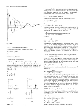
Figure 1.16 is called the dynamic magnifier. Resonance occurs when
w = w,. As the damping is increased the value of w for which
resonance occurs is reduced. There is also a phase shift as w
1.4.1.5 Forced undamped vibrations increases tending to a maximum of 7~ radians. It can be seen in
The equation of motion is given by (see Figure 1.17) Figure 1.18(a) that when the forcing frequency is high com-
pared to the natural frequency the amplitude of vibration is
mx + kx = Fo sin wt minimized.
or
1.4.1.7 Forced damped vibrations due to reciprocating or
rotating unbalance
x + w,2 = (Fdm) sin wt
Figure 1.19 shows two elastically mounted systems, (a) with
The solution to this equation is the excitation supplied by the reciprocating motion of a piston,
and (b) by the rotation of an unbalanced rotor. In each case
x = C sin o,t + D cos w,t + Fo cos wt/[m(w; - w’)]
the equation of motion is given by
where w is the frequency of the forced vibration. The first two
terms of the solution are the transient terms which die out, (M - m)i + ci + kx = (mew’) sin wt
leaving an oscillation at the forcing frequency of amplitude The solution of this equation is a sinusoid whose amplitude, X,
Fd[m(wf - 4 1 is given by
or X= mewL
V[(K - MJ)2 + (cw)2]
In representing this information graphically it is convenient to
plot MXlme against wlw, for various levels of damping (see
Figure l.20(a)). From this figure it can be seen that for small
FO sin wt Fo sin at values of w the displacement is small, and as w is increased the
displacement reaches a maximum when w is slightly greater
than w,. As w is further increased the displacement tends to a
constant value such that the centre of gravity of the total mass
M remains stationary. Figure 1.20(b) shows how the phase
angle varies with frequency.
1.4.1.8 Forced damped vibration due to seismic excitation
If a system as shown in Figure 1.21 has a sinusoidal displace-
ment applied to its base of amplitude, y, then the equation of
motion becomes
mx + ci + kx = ky + cy
The solution of this equation yields
’= J[(k- mw’)’ + (cw)’ 1
k2 + (cw)’
(a) Y
Figure 1.17 where x is the ampiitude of motion of the system.