
Page 20 - Mechanical Engineers Reference Book
P. 20
Vibrations 119
original plane would lead to what is known as dynamic 1.4 Vibrations
unbalan,ce.
To overcome this, the vector sum of all the moments about 1.4.1 Single-degree-of-freedom systems
the reference plane must also be zero. In general, this requires The term degrees of freedom in an elastic vibrating system is
two masses placed in convenient planes (see Figure 1.10). the number of parameters required to define the configuration
of the system. To analyse a vibrating system a mathematical
1.3.6.4 Balancing of reciprocating masses in single-cylinder model is constructed, which consists of springs and masses for
machines linear vibrations. The type of analysis then used depends on
the complexity of the model.
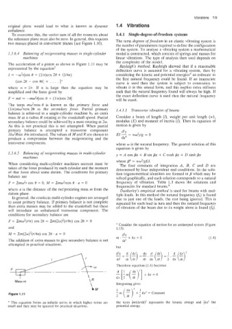
The accderation of a piston-as shown in Figure 1.11 may be Rayleigh’s method: Rayleigh showed that if a reasonable
represented by the equation> deflection curve is assumed for a vibrating system, then by
i = -w’r[cos B + (1in)cos 28 + (Mn) considering the kinetic and potential energies” an estimate to
the first natural frequency could be found. If an inaccurate
curve is used then the system is subject to constraints to
(cos 26 - cos 40) + , . . . ];k
where n = lir. If n is large then the equation may be vibrate it in this unreal form, and this implies extra stiffness
simplified and the force given by such that the natural frequency found will always be high. If
the exact deflection curve is used then the nataral frequency
F = mi = -mw2r[cos B + (1in)cos 201 will be exact.
The term mw’rcos 9 is known as the primary force and
(lln)mw2rcos 20 as the secondary force. Partial primary 1.4.1.1 Transverse vibration of beams
balance is achieved in a single-cylinder machine by an extra
mass M at a radius R rotating at the crankshaft speed. Partial Consider a beam of length (I), weight per unit length (w),
secondary balance could be achieved by a mass rotating at 2w. modulus (E) and moment of inertia (I). Then its equation of
As this is not practical this is not attempted. When partial motion is given by
primary balance is attempted a transverse component
d4Y
-
Mw’Rsin B is introduced. The values of M and R are chosen to EI - ww2y/g = 0
produce a compromise between the reciprocating and the dx4
transvense components. where o is the natural frequency. The general solution of this
equation is given by
1.3.6.5 Balancing of reciprocating masses in multi-cylinder y = A cos px + B sin px + C cosh px + D sinh px
machines
where p” = ww2igEI.
When considering multi-cylinder machines account must be The four constants of integration A, B, C and D are
taken of the force produced by each cylinder and the moment determined by four independent end conditions. In the solu-
of that force about some datum. The conditions for primary tion trigonometrical identities are formed in p which may be
balance are solved graphically, and each solution corresponds to a natural
F = Smw2r cos B = 0, M = Smw’rcos o . a = O frequency of vibration. Table 1.3 shows the solutions and
frequencies for standard beams.6
where a is the distance of the reciprocating mass rn from the Dunkerley’s empirical method is used for beams with mul-
datum plane. tiple loads. In this method the natural frequency vi) is found
In general, the cranks in multi-cylinder engines are arranged due to just one of the loads, the rest being ignored. This is
to assist primary balance. If primary balance is not complete repeated for each load in turn and then the naturai frequency
then extra masses may be added to the crankshaft but these of vibration of the beam due to its weight alone is found (fo).
will introduce an unbalanced transverse component. The
conditions for secondary balance are
F = Zm,w2(r/n) cos 20 = &~(2w)~(r/4n) cos 20 = o
* Consider the equation of motion for an undamped system (Figure
and 1.13):
M = Sm(2~)~(r/4n) cos 20 . a = 0 dzx
rn.-+lur=O
The addition of extra masses to give secondary balance is not d?
attempted in practical situations.
but
Y> W Therefore equation (1.4) becomes
I \
Mass m 1R
\ Integrating gives
LM
:I
Figure 1 1 krn ($)’+’,? 2 = Constant
* This equation forms an infinite series in which higher terms are the term &(dx/dt)* represents the kinetic energy and &xz the
small and they may be ignored for practical situations. potential energy.