
Page 18 - Mechanical Engineers Reference Book
P. 18
Dynamics of rigid bodies 1/7
I Normal
a
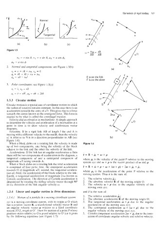
Figure 1.5
vx = v cos 6, vy = v sin 8, ax = a cos +,
ay := a sin 4
2. Normal and tangential components: see Figure 1.5(b):
v, = v..= r6 = ro, vn = 0
a, = rO, + ra + io,
a, = vB = rw' E is on the link
F is on the slider
3. Pobzr coordinates: see Figure 1.5(c):
vr = i, "8 = ~8
a, = i - rV, as = 4 + 2i.i
1.3.3 Circular motion
Circular motion is a special case of curvilinear motion in which
the radius of rotation remains constant. In this case there is an d
acceleration towards the cente of 0%. This gives rise to a force fl
towards the centre known as the centripetal force. This force is
reacted to by what is called the centrifugal reaction.
Veloc,ity and acceleration in mechanisms: A simple approach
to deter:mine the velocity and acceleration of a mechanism at a
point in time is to draw velocity and acceleration vector
diagrams.
Velocities: If in a rigid link AB of length 1 the end A is
moving with a different velocity to the end B, then the velocity
of A relative to B is in a direction perpendicular to AB (see
Figure 1.6).
When a block slides on a rotating link the velocity is made Figure 1.6
up of two components, one being the velocity of the block
relative to the link and the other the velocity of the link.
Accelerations: If the link has an angular acceleration 01 then
there will be two components of acceleration in the diagram, a r = 1 + pr + w x p
tangential component cul and a centripetal component of where pr is the velocity of the point P relative to the moving
magnitude w21 acting towards A. system xyz and w X p is the vector product of w and p:
When a block §!ides on a rotating link the total acceleration
is composed of four parts: first; the centripetal acceleration r = R + w x p + w x (w x p) + 2w x p, + pr
towards 0 of magnitude w21; second, the tangential accelera- where pr is the acceleration of the point P relative to the
tion al; third, the accelerarion of the block relative to the link; moving system. Thus r is the sum of:
fourth, a tangential acceleration of magnitude 2vw known as
Coriolis acceleration. The direction of Coriolis acceleration is 1. The relative velocity ir;
determined by rotating the sliding velocity vector through 90" 2. The absolute velocity R of the moving origin 0;
in the diirection of the link angular velocity w. 3. The velocity w x p due to the angular velocity of the
moving axes xyz.
1.3.4 Linear and angular motion in three dimensions and r is the sum of:
1. The relative acceleration Br;
1.3.4.1 Motion of a particle in a moving coordinate system
2. The absolute acceleration R of the moving origin 0;
xyz is a moving coordinate system, with its origin at 0 which 3. The tangential acceleration w x p due to the angular
has a position vector R, a translational velocity vector R and acceleration of the moving axes xyz;
an angular velocity vector w relative to a fixed coordinate 4. The centripetal acceleration w X (w x p) due to the
system XYZ, origin at 0'. Then the motion of a point P whose angular velocity of the moving axes xyz;
position vector relative to 0 is p and relative to 0' is r is given 5. Coriolis component acceleration 26.1 X pr due to the inter-
by the following equations (see Figure 1.7): action of coordinate angular velocity and relative velocity.