
Page 58 - Mechanical Engineers Reference Book
P. 58
Heat transfer 1/47
end the heat transfer rate is
Q = rnkABo tanh(rnl)
where 8 is the temperature difference between fin and fluid
and Bo is the difference at the fin root, rn = hp/kA, p is the fin
perimeter and A is the cross-sectional area.
A fin efficiency is then defined to compensate for the
varying temperature difference along the fin as -
Actual heat transfer rate
%in = - Parallel flow Counterflow
c---
Heat transfer rate if whole fin were at the wall temperature __c
which for the simple case above is yfin = tanh(rnl)/rnl. Fins are
usually fitted in arrays and the efficiency of a fin system can be i
established in the form of an area weighted fin efficiency, 7‘ 81
f
7’ = a& + 1 - P
where
totzl fin area Af,,
$=- __
-
totad area including fins A IParellel or counter
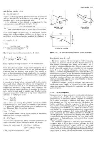
The U value based on the enhanced area A is then Figure 1.77 The mean temperature difference in heat exchangers
Heat transfer area A = ndl
The above equations will involve options with varying tube
numbers and diameters which will affect the determination of
For complete surfaces $ is supplied by the manufacturer. heat transfer coefficients (and hence the U-value), and a
number of solutions will be obtained. The optimum choice will
When fins of more complex shape are used (tapered fins or involve allowable pressure drops, velocities and exit tempera-
annular fins) the cross-sectional area is not constant and fin tures. It is not a difficult calculation, but, because of the
efficiency data are obtained from graphs. Care should be choice, a computer program may be used. There are short cuts
taken in the interpretation of such graphs since the equations to this approach based on the interrelation between pressure
above m,ay not agree with the definitions used for the graphs. drop and heat transfer (modified Reynolds’ analogy) to deter-
mine heat transfer coefficients and a method based on graphs
1.7.3.5 Heat exchangers” of effectiveness (E), capacity ratio (c) and number of transfer
units (NTU) is sometimes used.
It is possible to ‘design’ a heat exchanger with the information By whatever method a ’design’ is achieved, it will, unless the
above and obtain a basic idea of size and configuration of application is very simple, be necessary to consult a profes-
simple tubular structures. It is first necessary to realize that sional heat exchanger designer with experience and full com-
temperature differences change along a heat exchanger, and puter programs.
that flow may be parallel or counter in direction. The latter is
to be preferred, as it leads to smaller sizes. To allow for the
changing temperature difference a log mean temperature 1.7.4 Use of computers
difference is used (Figure 1.77): Computers may be used as an aid to heat transfer calculations
at various levels of skill. At the simplest level, computer
programs may be written for a home computer to determine,
for example, heat losses in buildings, heat inputs from pipes
and to allow for varying flow patterns (which are neither and radiators, etc. This will save repetitive calculations and
counter nor parallel flow) graphs are available to give a factor build a small library of useful programs. To aid those whose
F to modify the (usually) counterflow value of mean tempera- heat transfer and computing skills are slight Bacon” gives a
ture difference. Thus for any heat exchanger simple approach to problems. At a higher level of skill Adams
and Rogers” is a considerable advance in both programming
L,” F,~LMTD and heat transfer technique. Both books use BASIC and the
If an estimated mean U-value for the surface is then deter- latter emphasizes the finite difference technique. Both books
mined tlhe heat exchange equation is include programs. Supplementary reading from other heat
transfer books would be advantageous. For more detail on the
Q = UA FBLMro mathematics of finite difference techniques in heat transfer
Myers2’ is useful.
Thus the area is determined. There are many solutions to this An alternative approach to numerical approximations in
equation to satisfy all the constraints which will include:
computer work is to use finite element methods. For heat
Energy for each stream Q = (hdA)h,, = (hAh),,ld transfer applications Myers” is again useful. Very few people
will find the need for finite element programming skills as
(Ah = enthalpy change)
there is an ever-increasing range of software which is aimed at
Continuity of each stream h = pAV the solution of many engineering problems, including heat