
Page 193 - Mechanical Engineers' Handbook (Volume 2)
P. 193
182 Temperature and Flow Transducers
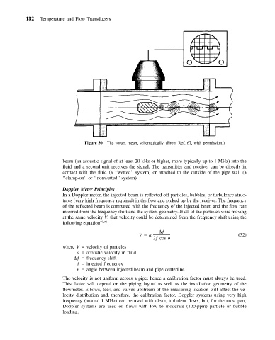
Figure 30 The vortex meter, schematically. (From Ref. 67, with permission.)
beam (an acoustic signal of at least 20 kHz or higher, more typically up to 1 MHz) into the
fluid and a second unit receives the signal. The transmitter and receiver can be directly in
contact with the fluid (a ‘‘wetted’’ system) or attached to the outside of the pipe wall (a
‘‘clamp-on’’ or ‘‘nonwetted’’ system).
Doppler Meter Principles
In a Doppler meter, the injected beam is reflected off particles, bubbles, or turbulence struc-
tures (very high frequency required) in the flow and picked up by the receiver. The frequency
of the reflected beam is compared with the frequency of the injected beam and the flow rate
inferred from the frequency shift and the system geometry. If all of the particles were moving
at the same velocity V, that velocity could be determined from the frequency shift using the
following equation 70,71 :
ƒ
V a (32)
2ƒ cos
where V velocity of particles
a acoustic velocity in fluid
ƒ frequency shift
ƒ injected frequency
angle between injected beam and pipe centerline
The velocity is not uniform across a pipe; hence a calibration factor must always be used.
This factor will depend on the piping layout as well as the installation geometry of the
flowmeter. Elbows, tees, and valves upstream of the measuring location will affect the ve-
locity distribution and, therefore, the calibration factor. Doppler systems using very high
frequency (around 1 MHz) can be used with clean, turbulent flows, but, for the most part,
Doppler systems are used on flows with low to moderate (100-ppm) particle or bubble
loading.