
Page 321 - Mechanical Engineers' Handbook (Volume 2)
P. 321
312 Mathematical Models of Dynamic Physical Systems
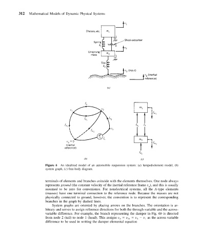
Figure 6 An idealized model of an automobile suspension system: (a) lumped-element model, (b)
system graph, (c) free-body diagram.
terminals of elements and branches coincide with the elements themselves. One node always
represents ground (the constant velocity of the inertial reference frame v ), and this is usually
g
assumed to be zero for convenience. For nonelectrical systems, all the A-type elements
(masses) have one terminal connection to the reference node. Because the masses are not
physically connected to ground, however, the convention is to represent the corresponding
branches in the graph by dashed lines.
System graphs are oriented by placing arrows on the branches. The orientation is ar-
bitrary and serves to assign reference directions for both the through-variable and the across-
variable difference. For example, the branch representing the damper in Fig. 6b is directed
from node 2 (tail) to node 1 (head). This assigns v v 21 v v as the across-variable
1
2
b
difference to be used in writing the damper elemental equation