
Page 325 - Mechanical Engineers' Handbook (Volume 2)
P. 325
316 Mathematical Models of Dynamic Physical Systems
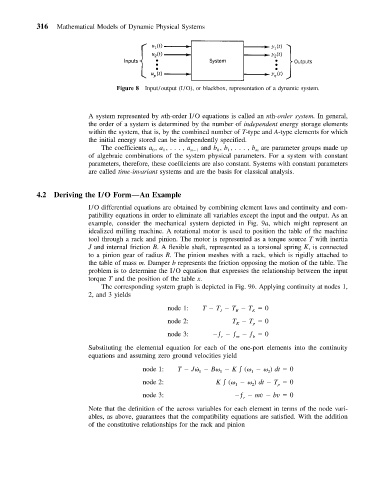
Figure 8 Input/output (I/O), or blackbox, representation of a dynamic system.
A system represented by nth-order I/O equations is called an nth-order system. In general,
the order of a system is determined by the number of independent energy storage elements
within the system, that is, by the combined number of T-type and A-type elements for which
the initial energy stored can be independently specified.
The coefficients a , a ,... , a n 1 and b , b ,..., b are parameter groups made up
1
m
0
1
0
of algebraic combinations of the system physical parameters. For a system with constant
parameters, therefore, these coefficients are also constant. Systems with constant parameters
are called time-invariant systems and are the basis for classical analysis.
4.2 Deriving the I/O Form—An Example
I/O differential equations are obtained by combining element laws and continuity and com-
patibility equations in order to eliminate all variables except the input and the output. As an
example, consider the mechanical system depicted in Fig. 9a, which might represent an
idealized milling machine. A rotational motor is used to position the table of the machine
tool through a rack and pinion. The motor is represented as a torque source T with inertia
J and internal friction B. A flexible shaft, represented as a torsional spring K, is connected
to a pinion gear of radius R. The pinion meshes with a rack, which is rigidly attached to
the table of mass m. Damper b represents the friction opposing the motion of the table. The
problem is to determine the I/O equation that expresses the relationship between the input
torque T and the position of the table x.
The corresponding system graph is depicted in Fig. 9b. Applying continuity at nodes 1,
2, and 3 yields
node 1: T T T T 0
J B K
node 2: T T 0
K p
node 3: ƒ ƒ ƒ 0
r m b
Substituting the elemental equation for each of the one-port elements into the continuity
equations and assuming zero ground velocities yield
node 1: T J˙ B K ( ) dt 0
2
1
1
1
node 2: K ( ) dt T 0
2
p
1
node 3: ƒ m˙v bv 0
r
Note that the definition of the across variables for each element in terms of the node vari-
ables, as above, guarantees that the compatibility equations are satisfied. With the addition
of the constitutive relationships for the rack and pinion