
Page 395 - Mechanical Engineers' Handbook (Volume 2)
P. 395
386 Basic Control Systems Design
Figure 4 Feedback compensation of an amplifier.
and transient performance specifications such as the damping ratio , natural frequency ,
n
dominant time constant , maximum overshoot, settling time, and bandwidth. The above
material is reviewed in the previous chapter. Treatment in depth is given in Refs. 1–4.
2 CONTROL SYSTEM STRUCTURE
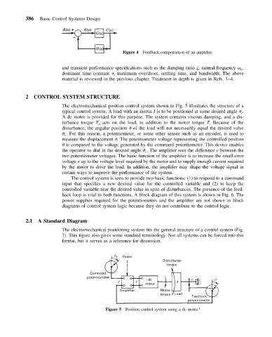
The electromechanical position control system shown in Fig. 5 illustrates the structure of a
typical control system. A load with an inertia I is to be positioned at some desired angle .
r
A dc motor is provided for this purpose. The system contains viscous damping, and a dis-
turbance torque T acts on the load, in addition to the motor torque T. Because of the
d
disturbance, the angular position of the load will not necessarily equal the desired value
. For this reason, a potentiometer, or some other sensor such as an encoder, is used to
r
measure the displacement . The potentiometer voltage representing the controlled position
is compared to the voltage generated by the command potentiometer. This device enables
the operator to dial in the desired angle . The amplifier sees the difference e between the
r
two potentiometer voltages. The basic function of the amplifier is to increase the small error
voltage e up to the voltage level required by the motor and to supply enough current required
by the motor to drive the load. In addition, the amplifier may shape the voltage signal in
certain ways to improve the performance of the system.
The control system is seen to provide two basic functions: (1) to respond to a command
input that specifies a new desired value for the controlled variable and (2) to keep the
controlled variable near the desired value in spite of disturbances. The presence of the feed-
back loop is vital to both functions. A block diagram of this system is shown in Fig. 6. The
power supplies required for the potentiometers and the amplifier are not shown in block
diagrams of control system logic because they do not contribute to the control logic.
2.1 A Standard Diagram
The electromechanical positioning system fits the general structure of a control system (Fig.
7). This figure also gives some standard terminology. Not all systems can be forced into this
format, but it serves as a reference for discussion.
Figure 5 Position control system using a dc motor. 1