
Page 393 - Mechanical Engineers' Handbook (Volume 2)
P. 393
384 Basic Control Systems Design
12.1 Digital Control Hardware 434 13.2 Software for Control
12.2 Software for Digital Control 436 Systems Simulation 438
12.3 Embedded Control Systems
and Hardware-in-the-Loop 14 FUTURE TRENDS IN
Testing 438 CONTROL SYSTEMS 439
14.1 Fuzzy Logic Control 441
13 SOFTWARE SUPPORT FOR 14.2 Nonlinear Control 441
CONTROL SYSTEM DESIGN 438 14.3 Adaptive Control 441
13.1 Software for Graphical 14.4 Optimal Control 442
Design Methods 438
REFERENCES 442
1 INTRODUCTION
The purpose of a control system is to produce a desired output. This output is usually
specified by the command input and is often a function of time. For simple applications in
well-structured situations, sequencing devices like timers can be used as the control system.
But most systems are not that easy to control, and the controller must have the capability
of reacting to disturbances, changes in its environment, and new input commands. The key
element that allows a control system to do this is feedback, which is the process by which
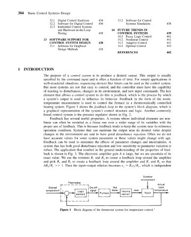
a system’s output is used to influence its behavior. Feedback in the form of the room-
temperature measurement is used to control the furnace in a thermostatically controlled
heating system. Figure 1 shows the feedback loop in the system’s block diagram, which is
a graphical representation of the system’s control structure and logic. Another commonly
found control system is the pressure regulator shown in Fig. 2.
Feedback has several useful properties. A system whose individual elements are non-
linear can often be modeled as a linear one over a wider range of its variables with the
proper use of feedback. This is because feedback tends to keep the system near its reference
operation condition. Systems that can maintain the output near its desired value despite
changes in the environment are said to have good disturbance rejection. Often we do not
have accurate values for some system parameter or these values might change with age.
Feedback can be used to minimize the effects of parameter changes and uncertainties. A
system that has both good disturbance rejection and low sensitivity to parameter variation is
robust. The application that resulted in the general understanding of the properties of feed-
back is shown in Fig. 3. The electronic amplifier gain A is large, but we are uncertain of its
exact value. We use the resistors R and R to create a feedback loop around the amplifier
2
1
and pick R and R to create a feedback loop around the amplifier and R and R so that
1
2
1
2
AR /R 1. Then the input–output relation becomes e R e /R , which is independent
2
1
1 i
2
o
Figure 1 Block diagram of the thermostat system for temperature control. 1